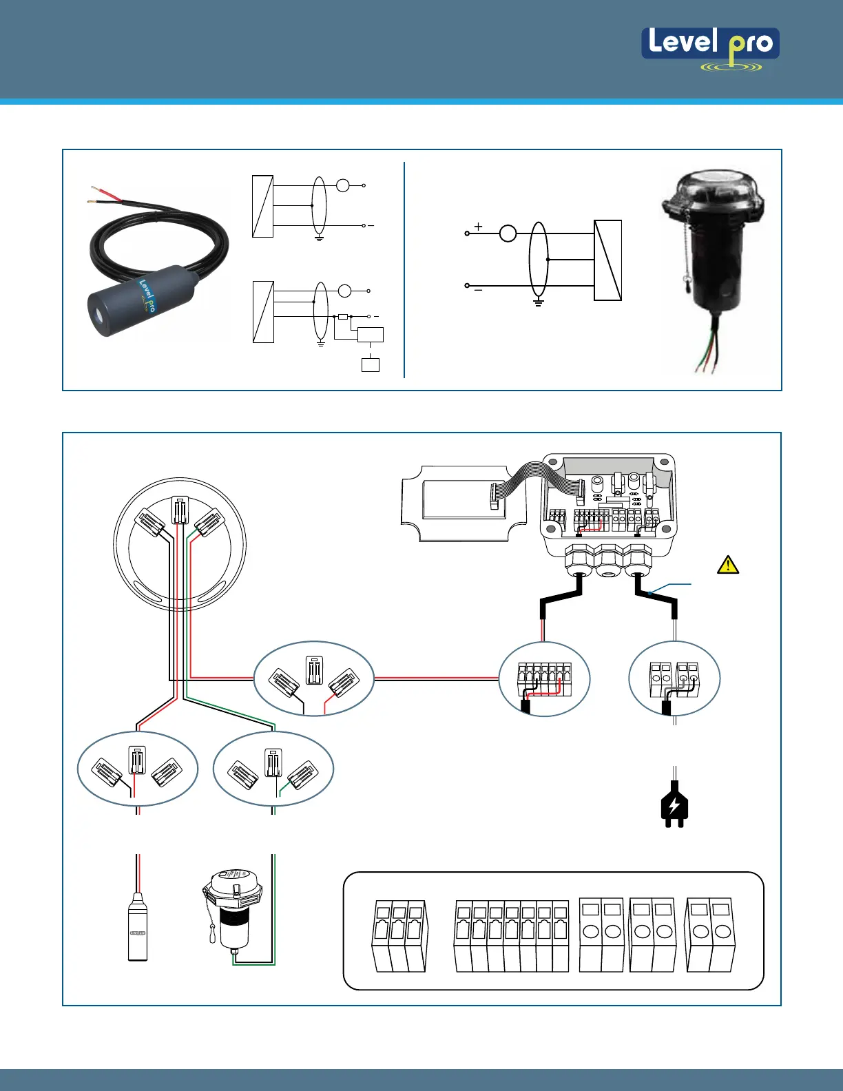
4.2 Connection Diagram
13141516 12 11 10 09 08 07 06 05 04 03 02 01
Power Supply
120VAC
04 03 02 01
TVF Terminals
Red wire Terminal 8
Black Wire Terminal 11
Junction Box Terminals
Red wire Terminal 6
Black Wire Terminal 1
TVF Terminals
Black Wire Terminal 1
White Wire Terminal 2
Sentinel LTE Telemetry100 Series
120 VAC Power Supply
TVL Channel Terminals
Junction Box Terminals
1
2
3 4
5 6
Junction Box Terminals
Green wire Terminal 5
Black Wire Terminal 4
Junction Box Terminals
Red wire Terminal 3
Black Wire Te
rminal 2
13 12 11 10 09 08 07
1
2
3 4
5 6
1
2
3 4
5 6
1
2
3 4
5 6
4.1 Wiring Diagram
2-wire-system (current)
P
Supply +
+
Supply -
V
s
I
(Red)
(White)
A
24VDC
2-wire-system
(current) HART.
V
s
Supply +
Supply -
P
+
I
Inferface
HART
PC
R
A
24VDC
2-Wire-System | 4-20mA
Sentinel LTE
Telemetry
Supply +
Supply -
V
s
Green
Black
100 Series with Sentinel LT Series
100 Series Sentinel LT Series
Continuous Submersible Level Transmitter
Levelpro-Sensors Manual
05
© Icon Process Controls Ltd. All Rights Reserved