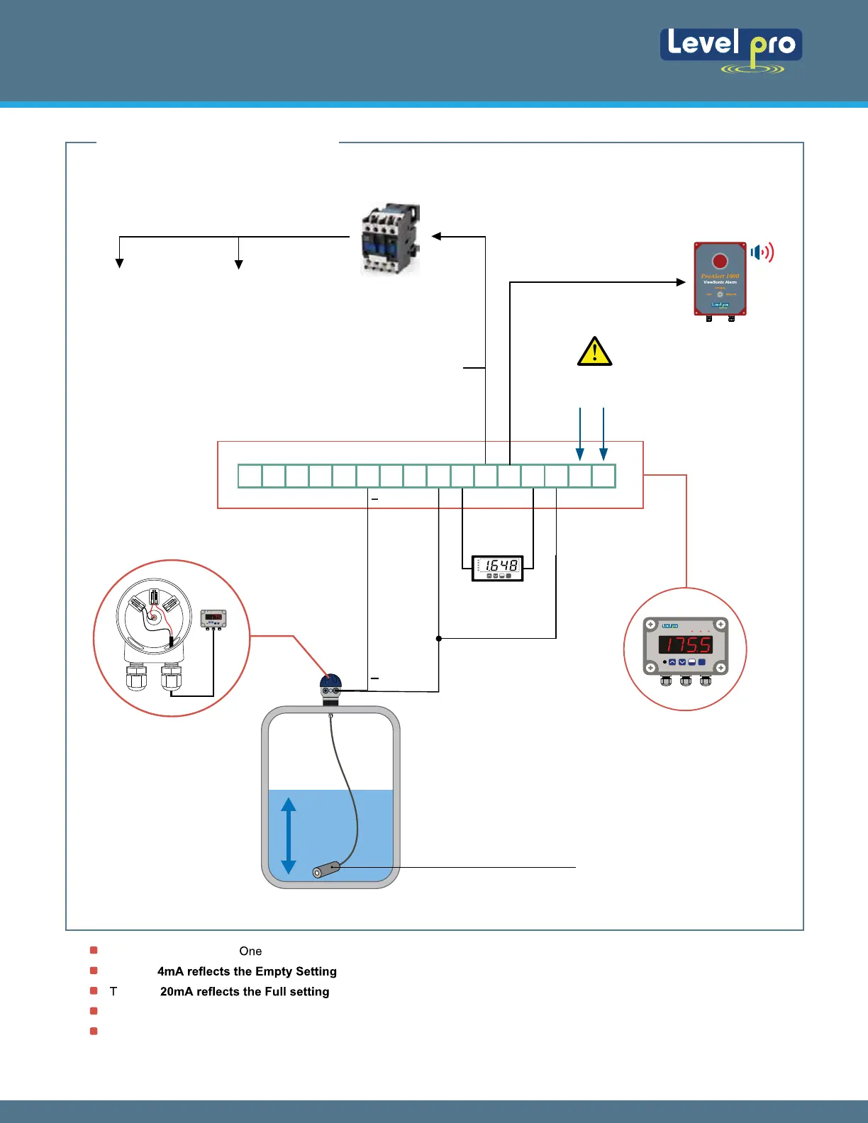
The default for the Input is 4 mA and this will not change.
Typically
will be the tank is empty (example. 000.0 Gallons, 000.0 inches, 000.0 feet etc.).
ypically will be when the tank is full (example: 500.0 Gallons, 120.0 inches, 10.0 feet, etc.)
Shielded cable is recommended for control loop wiring.
Use the Red wire as the (+) and the Black wire as the (-)
Wiring to the Levelpro Series Tank Level Controller
External
Display
-
+
+
+
4-20
Output
Examples : Pump Shut-Off
High Level Alarm
4. WIRING DIAGRAM
Wiring to a Loop Powered Display :
AL R1 R2
MENU
ESC
ENTER
100 Series Level Sensors
1 2
3 4
5 6
AL R1 R2
MENU
ESC
ENTER
16 15 14 13 12 11 10 9 8 7 6 5 4 3 2 1
Power Supply 120VAC
Terminal 1 & 2
TVL Channel Terminals
TVL Series
Level Process Display | Controller
Jump Wire
3 & 8
Alarm
Pump
Magnetic
Contactor Relay
Alarm
ProAlert-1000
Audible / Vesual
Output Relays
Output Relays
Wiring LP 100
Junction Box
MENU
ESC
ENTER
Continuous Submersible Level Transmitter
Levelpro-Sensors Manual
04
© Icon Process Controls Ltd. All Rights Reserved