Each of the four dimmer channels of the DDS 6000 may be operated by an analog 0 - 10 VDC control voltage. This type of control
will provide 0% intensity at 0 volts and 100% intensity at 10 volts. Any or all of the DDS 6000 dimmer channels may be operated
in this manner simultaneously with any multiplex control input. Each dimmer will respond to the greater of any control inputs.
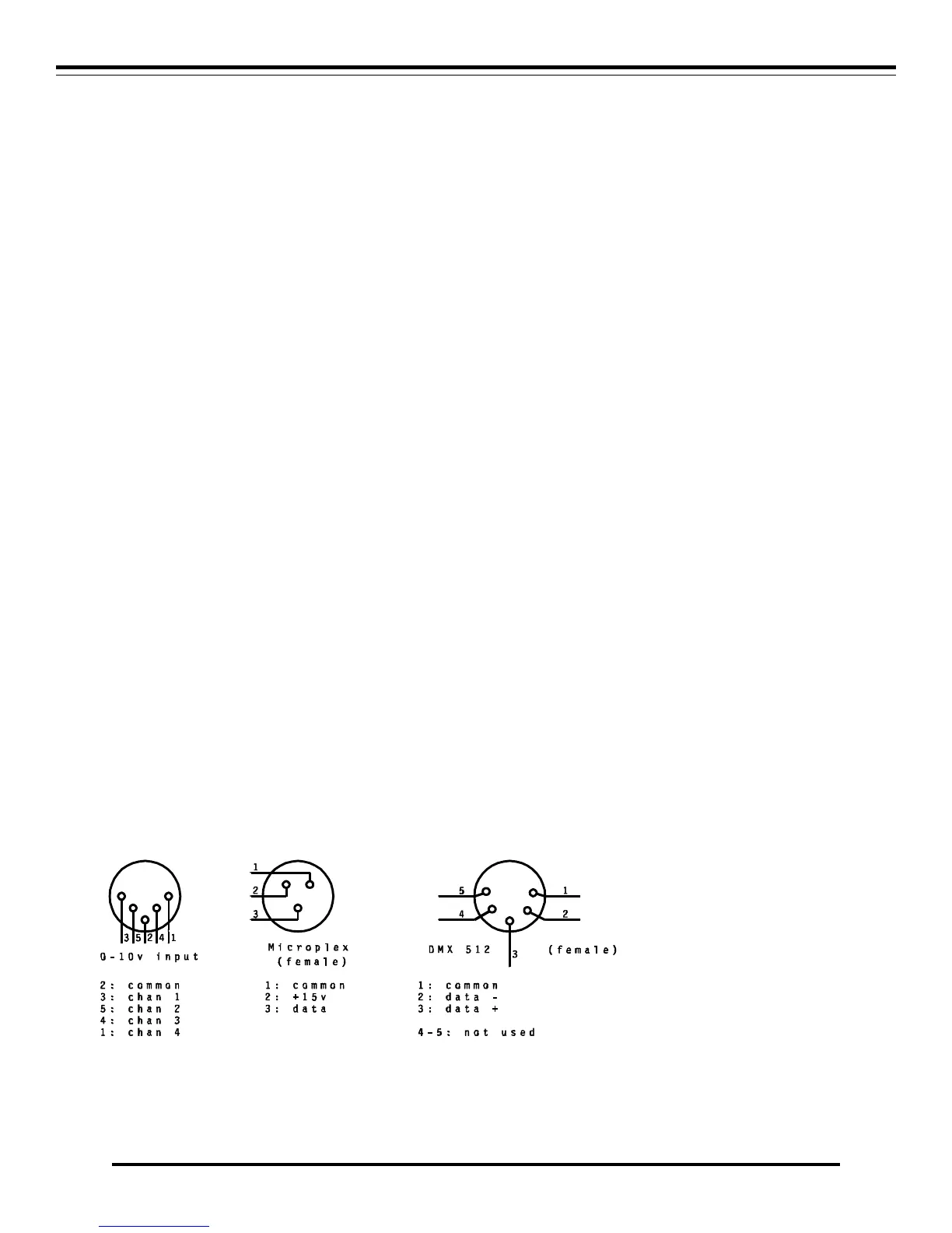
The analog control input uses a standard 5 pin DIN plug which is available from most electronics supply houses. Connect each of
the positive channel control wires to the desired dimmer channel input pins (see diagram) of the plug. Connect the common (ground)
control wire to the pin indicated on the diagram. Consult the documentation of the analog control console or device you are using
for the proper connections. The control input impedance is 4.7K ohms.
DMX-512 MULTIPLEX CONTROL WIRING.
DMX 512 is the United States Institute of Theater Technology (USITT) standard for the digital control of dimmers. NSI DDS
Dimmer products can be converted from Microplex to DMX 512 digital multiplex with a simple kit available from your dealer.
DMX-512 is the preferred type of control wiring when many dimmer channels are used, because of the high update rate and the
resistance to interference. It is recommended in locations subject to electrical noise. DMX-512 only requires 3 wires to transmit
lighting levels for as many as 512 dimmer channels. Most of the NSI lighting control consoles can optionally use this interface.
Connect the DMX 512 cable from the control console to the male input connector. Another cable may be connected from the
female connector to the male connector on another pack. Many dimmer packs may be "daisy chained" connect together in this
manner.
Be sure to set the Channel Address dip switch as required (see DIP SWITCH SETTINGS).
LED INDICATORS
The front panel indicator LEDs indicate the status of the dimmer.
• RED - Indicates the firing card is receiving DC power.
• GREEN - Steady indicates a multiplex control signal is being received.
• YELLOW - Indicates a respective dimmer channel is active and the LED indicates relative intensity.
AUTO LAMP TEST
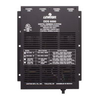
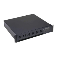
DDS 6000 DIMMER PACK
DMX-512 MULTIPLEX CONTROL WIRING. Software Revision 1.0 and above, Version C, UL Versions
4 NSI CORPORATION