Page 5
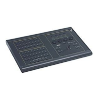
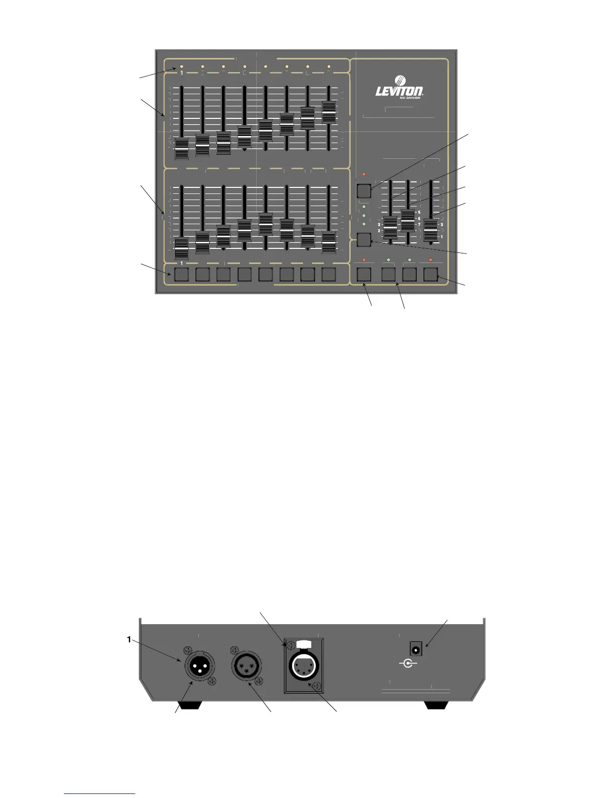
6. Mode Button: This button sequences the console through the 3 operating modes. The lit LED
indicates the current mode.
7. Tap Sync: Repeatedly tapping this button establishes the chase rate.
8. Chase 1: This button toggles Chase 1 on and off, indicated by the LED.
9. Chase 2: This button toggles Chase 2 on and off, indicated by the LED.
10. X Crossfader: This slide control is used to proportionally vary the intensity of Scene X.
11. Y Crossfader: This slide control is used to proportionally vary the intensity of Scene Y.
12. Master: This slide control is used to proportionally vary the overall console intensities to
stage except those from the Bump buttons.
13. Blackout: This button is used to kill all output to stage except from the Bump buttons. The
console is in Blackout whenever the Blackout LED is lit.
Rear Panel
1. Microplex Outputs: These 2 outputs provide Leviton-NSI’s microphone dimmer connection via a
3-pin XLR type connector. Either connector may be used (1-Male, 1-Female).
2. DMX512: This optional output is used to provide dimmer control information to dimmers
using this protocol. Its 5 pin Female XLR connector conforms to the USITT
standard.
3. AUX DC Power: This input jack allows a standard wall transformer rated at 15v DC (at least
200 MA) to provide power to the MC 7000 Series Console.
P