Automatic Operation
Sensor analyzes room
and sets sensitivity to
optimal setting
Same as above
Timer setting generally
increased during learning
period, then decreases to
minimize "on" time
No automatic operation
Conditions Analyzed in
Automatic Operation
Air currents
False-on occurrences
False-off "
Room (surface) temp
Lens dirt
Signal to noise ratio
False-off occurrences
Error free operation
decreases the timer
setting
N/A
Knob Setting Under
Manual Operation**
Linear range setting
Full CCW = min (off)
Full CW = max range
Linear range setting
Full CCW = min .)
Full CW = max (30 min.)
Linear range setting
Full CCW = min daylight
Full CW = max (off)
Function
Sets the ultrasonic range
Sets the infrared range
Sets the length of time
lights will remain on after
last motion is sensed
Sets level of daylight
needed to prevent the
lights from turning on
Recommended
Manual Setting
50%
75%
33%
10 min.
Off
unless
used
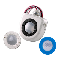
Knob Color:
Control
Green:
Ultrasonic
Sensitivity
Red:
Infrared
Sensitivity
Black:
Timer
Blue:
Photocell
Same as above
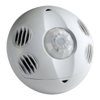
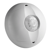
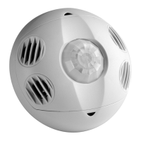
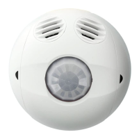
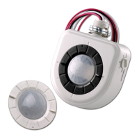
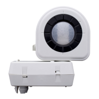
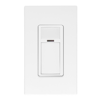
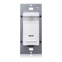
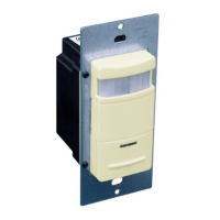
CONTROLS
Models
Part Number Coverage Transducer Pairs Operating Frequency Infrared Lens Additional Features
OSC05-M 500 sq. ft. One 40kHz Extended Range Photocell
OSC10-M 1000 sq. ft. Two 40kHz Extended Range Photocell
OSC20-M 2000 sq. ft. Two 32kHz Extended Range Photocell
OSCxx-MOW
.........................
**When a function is set to “Automatic Operation” the initial setting is determined by the position of the knob. CCW is counter clockwise, CW is clockwise
Leviton Mfg. Co., Inc.
59-25 Little Neck Pkwy • Little Neck, NY 11362-2591 • Tech Line: 1-800-824-3005 • Fax: 1-800-832-9538
Visit our Website at: www.leviton.com
JOB NAME:
JOB NUMBER:
CATALOG NUMBERS:
SPECIFICATION SUBMITTAL
Product
Specifications
DIP switch settings
Switch Switch Functions Switch Settings
Bank A OFF ON
A1 Single/Multi-Tech Mode Multi-Tech Single Tech
A2 PIR/Ultrasonic Mode PIR Ultrasonic
A3 Manual Mode Auto Adapting Enabled Auto Adapting Disabled
A4 Walk-Thru Disable Walk-Thru Enabled Walk-Thru Disabled
Bank B
B1 Override to On Auto Mode Lights forced On
B2 Override to Off Auto Mode Lights forced Off
B3 Test Mode OFF¡ON¡OFF Enter/Exit Test Mode
B4 LED Disable LEDS Enabled LEDS Disabled
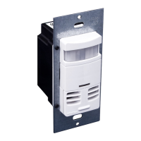
NOTE: Sensor activates upon infrared detection. Place sensors to provide infrared coverage at room entrances.
 Loading...