10
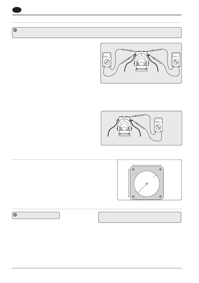
Test 1. Fig.4.5.1
With the negative not connected and the positive
cable connected but with battery switch off or fuse
removed. Use a continuity tester to check for a
connection between the –VE stud and motor body
and also between +VE stud and motor body. In both
cases the meter should give no indication of an
electrical connection.
If a connection is measured between the +VE stud
and the motor body, check installation for cables
or wires touching the assembly or for damage to
assembly.
If a connection is measured between the –VE stud
and the motor body, remove any bonding straps at-
tached to the assembly and check as before.
Test 2. Fig 4.5.2
With the batter y applied: Use a voltmeter to test
the voltage between the –VE motor stud and the
thruster motor body. If the supply voltage (12 V/24
V) is measured, disconnect power immediately
and inspect the assembly for faulty installation or
damage.
4.5 Electrolytic test
To prevent electrolytic corrosion or faults, the thruster motor body and assembly MUST remain isolated
from any power supply or grounds. The installer can check for this using a multimeter in the following ways.
Ω
Ω
V
Refer to the cutting template opposite, use a
50mm (2”) hole saw and a 3mm drill for mounting
screws
Mount on a clean flat surface
Connect panel wiring loom to the plug and play
thruster control loom
4.6 Installing control panel
Check list electrical
Check motor connections are tight with rubber boots
in place.
The correct fuse is in place.
Check all switch wires are connected to correct
motor terminal.
Now the cables can be connected to the battery.
Operation of electrical unit
Ensure batteries are fully charged before switching
on the main power.
Before operating the thruster, check that the water
is free from swimmers, divers or debris and make
sure you are not close to other vessels.
4.7 Final checks
Check the power is OFF The thruster must not be operated unless it is
in water.
Fig 4.5.1
Fig 4.5.2
Fig 4.6
50mm (2”)
53mm (2 ¹/₁₆”)
53mm (2 ¹/₁₆”)
GB
 Loading...