6
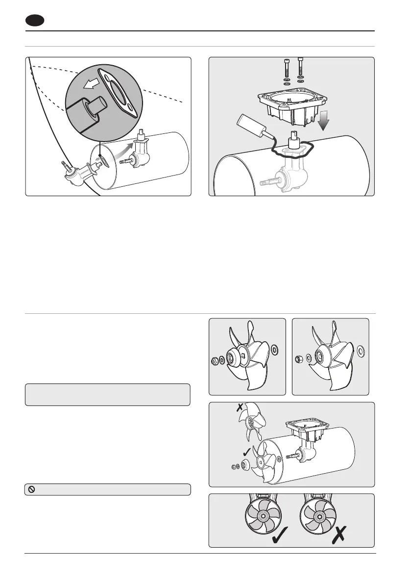
3.5 Propeller assembly
GB
NOTE: Illustrations based on 140TT saddle.
To suit the wiring configuration supplied fit the
thruster propeller on the port side.
Place gasket on hub and locate through centre
hole. Sealant can be applied to gasket and flange
to aid sealing.
NOTE: To achieve the correct position of the propeller
in the tunnel the gasket must be inplace.
Check the hub gasket is in place.
Fig 3.5.1 - Assemble propeller as shown: nyloc nut
onto propeller shaft.
Note: Tighten each bolt alternately a number of
times to full torque.
NOTE: Poor exterior tunnel surface could cause
leakage and noise. Apply sealant to this area as
required (Fig. 3.4.2).
Apply zinc chromate paste or marine grease to
location bore and assemble saddle onto hub
(SikaFlex® or similar maybe used to seal saddle in
place). Apply Blue Loctite® 243 to bolts and hand
tighten along with supplied washers (Fig. 3.4.2).
NOTE: Tighten to full torque within 10 minutes.
3.4 Installing hub unit and saddle
Check the propeller has been assembled in the
correct order.
Fig 3.5.2 - Tighten hub/saddle bolts to
5 Nm (3.7 lbs.) for 110
9 Nm (6.6 lbs.ft) for 140
Check that propeller is centred and free turning
(within 10 minutes of applying Blue Loctite® 243).
Antifoul propeller if desired.
DO NOT allow propeller to touch tunnel.
110TT140TT
Fig 3.4.1 Fig 3.4.2
Fig 3.5.2
Fig 3.5.1
Fig 3.5.3
 Loading...