Lewmar Thruster 110TT and 140TT 2.0 Manual ref B10417 iss.2 | 5
3.3 Preparing for fitting the thruster
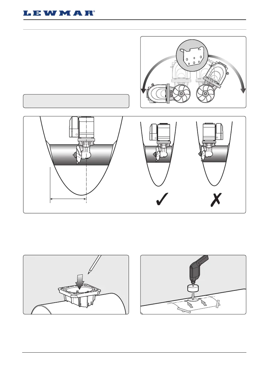
Fig 3.3.1
Fig 3.3.2
Fig 3.3.3 Fig 3.3.4
The Thruster can be installed at any angle within 90°
from vertical.
Choose position of thruster, ensuring internal room for motor and controls and that the propeller is easily
reached from outside.
NOTE: Fig 3.3.2. - Normal install is to Port
Place the thruster saddle in the desired position,
ensure the fit is firm and free from movement then
mark centre.
To aid installation a kit is available. See Sec 6.6
Accessories.
Position template on centre line, double check
everything and drill. Remove all burrs. All the holes
must be on the centre line. Poor alignment may
affect hub positioning.
Electric motors must be supported if installed
more than 30° from vertical (Fig 3.3.1).
600 mm
(24”) Max
 Loading...