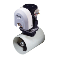
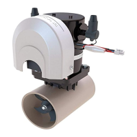
Lewmar Thruster 110TT and 140TT 2.0 Manual ref B10417 iss.2 | 3
This manual forms part of the product and MUST BE RETAINED along with,
OR incorporated into, the Owner’s Manual for the vessel to which the thruster is fittted.
A competent, marine engineer must carry
out any work on the hull of your boat.
The boat MUST be out of the water,
levelled and secure in its cradle.
3- Installation
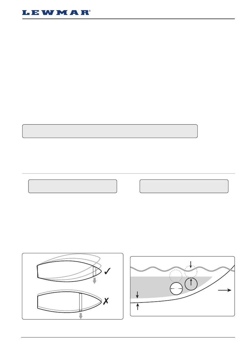
The actual position of the Thruster will depend on the internal & external construction of the Motor Boat or Sail-
ing Yacht. For optimal performance the Thruster should be mounted within the following:
As far forward as possible (Fig 3.1.1 / lever effect).
1 x Ø below the waterline to prevent air being sucked into the tunnel. (Fig. 3.1.2 / 0.75 x Ø minimum.).
Minimum suggested tunnel length 2 x Ø.
NOTE: Ensure there is sufficient space for the Thruster assembly complete with motor and controls in the boat.
Ø = Tunnel Diameter
3.1 Choosing the location
It is very dangerous to run the thruster out of the water, even for a few seconds, the motor will over speed
by 300%, causing damage to the motor seals etc. and the propeller will cause serious damage to whatever
comes into contact with it. This action will invalidate the warranty.
Consult the boat manufacturer if you have any doubt about the strength or suitability of the mounting
location.
Electrical
Make sure you have switched off the power before you start installing this product.
If in doubt about installing electrical equipment please seek advice from a suitably qualified electrical
engineer.
To the best of our knowledge, the information in this manual was correct when it went to press. However, Lew-
mar cannot accept liability for any inaccuracies or omissions it may contain.
In addition, our policy of continuous product improvement may change specifications without notice. As a result,
Lewmar cannot accept liability for any differences between the product and the manual.
Optimum area
Min 100mm (4”)
Min 0.75 x Ø
Fig 3.1.1
Fig 3.1.2
 Loading...