Electrical symbols
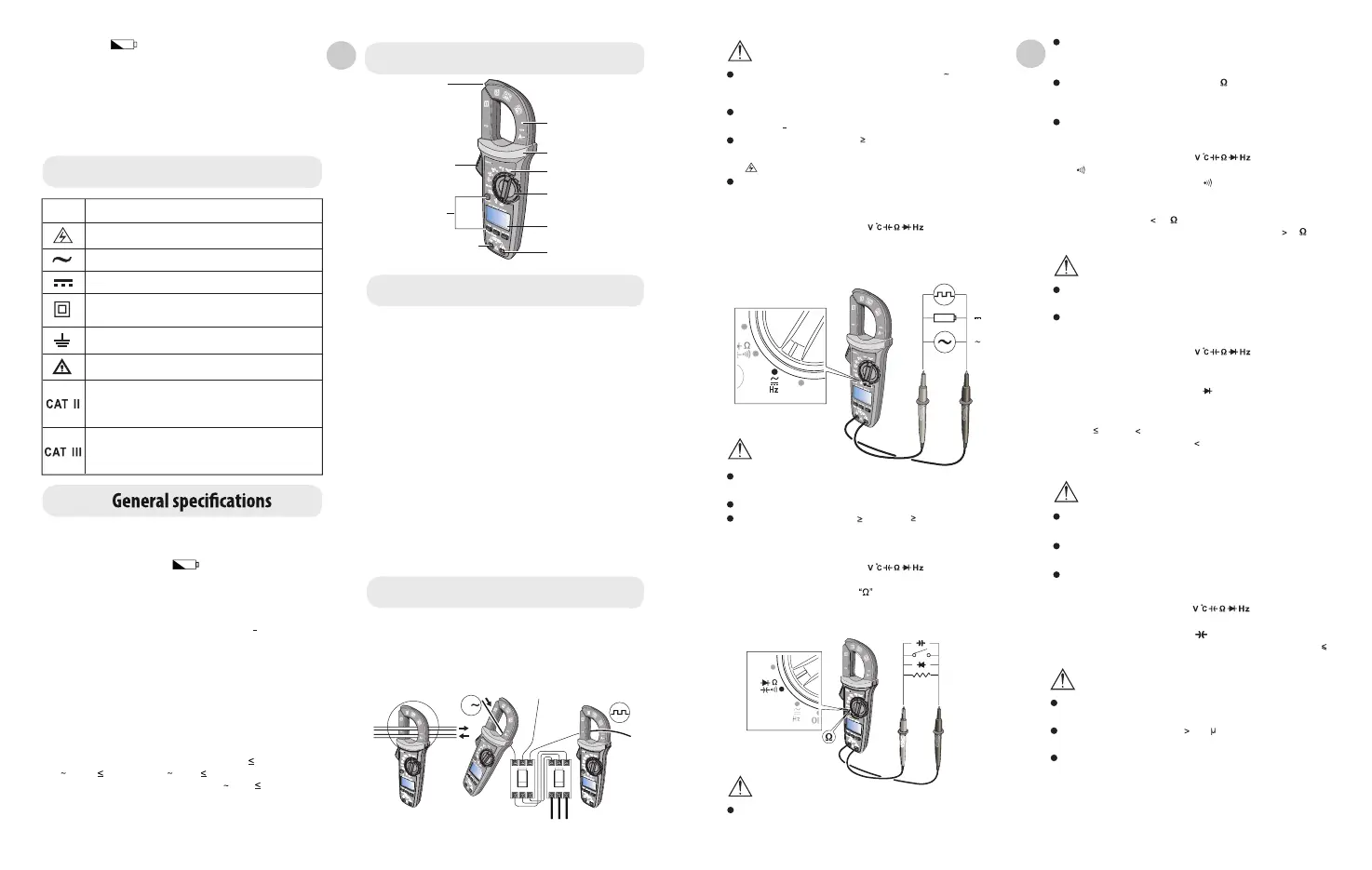
External structure
NCV sensing end
Clamp jaws
Hand guard
LED indicator
Jaw opening trigger
Function switch
Function buttons
LCD display
Positive (+) input
jack
Picture 1
COM (negative -) input jack
-
-
-
-
-
-
-
-
-
0 -
1 -
2 -
3 -
11 -
12 -
13 -
When the « » symbol appears on tge LCD, please replace
the batteries in time to ensure measurement accuracy. If the meter
is not in use for a long time, please remove the batteries.
Do not change the internal circuit of the meter to avoid damage
meter and user.
Do not use or store the meter in high temperature, high humidity,
flammable, explosive and strong magnetic field environments.
Clean the meter casing with a soft cloth and mild detergent. Do not
use abrasives or solvents!
Polarity display : Auto
Overload display : «OL» or (-OL)
Low battery indication : the « » symbol is displayed.
Low battery shutdown prompt : The «Lo.bt» interface appears on the
LCD and lasts for about 10s, the buzzer beeps three times, and the
meter automatically shuts down.
Test position error : If the source under test is not placed at the
center of the clamp jaws when measuring current, + 1,0% additional
error in reading will be produced.
Drop protection : 1m
The maximum size of jaw opening : 28 mm in diameter
Battery ; AAA battery 1.5V x 2
Auto power off : If there is no operation of the function switch or any
button for 15 minutes, the meter will automatically power off. This
function can be turned off as needed.
Weight : about 248g (including batteries).
Altitude : 2000m
4 -
5 -
6 -
Operating temperature and humidity: 0°C-30°C ( 80% RH), 30°C
40°C) ( 75% RH), 40°C 50°C ( 45% RH)
Storage temperature and humidity: -20°C 60°C ( 80% RH)
Electromagnetic compatibility:
RF = 1V/m, overall accuracy = specified accuracy + 5% of range
RF = 1Vm, no specified calculation
Symbol Description
Caution, possibility of electric shock
Alternating current
Direct current
Earth (ground) TERMINAL
Warning or Caution
Equipment protected throughout by
INSULATION or REINFORCED INSULATION
It is applicable to test and measuring circuits connected
directly to utilization points (socket outlets and similar
points) of the liw-voltage MAINS installation
It is applicable to test and measuring circuits connected to
the distribution part of the building’s low-coltage MAINS
installation
Max display: 6099 (LX-M-2100)
Dimensions : 215,1mm x 72,5mm x 37,8mm
EN
Button description
Operating instructions
Short press this button to enter/exit the data hold mode, and long press
(about 2s) this button to turn on/off the backlight (the backlight will
automatically turn off after 60s).
1 - SELECT button
1 - AC Current/Current frequency measurement (Picture 2)
2 - HOLD/BACKLIGHT - SELECT button
Short press this button to enter the maximum/minimum measurement
mode and long press this button to exit (only valid for AC/DC voltage, AC
current, resistance and temperature measurement).
3 - MAX/MIN button
In the cappacitance and voltage positions, press this button to store the
current reading as a reference for future readings. When the LCD display
value is reset to zero, the stored reading will be subtracted from the
future readings. Press this button again to exit the relative value mode.
1 -
2 -
Select the AC current range (6A/60A/600A.)
Press the trigger to open the clamp jaws, and fully enclose one
conductor
4 - REL. button
In the composite function position, press this button to switch
the corresponding measurement functions : in the AC/DC/Hz
short press this button to switch between the AC and DC finctions,
long press (about 2s) this button to enter/exit the Hz
function.
AC current
measurement
Current frequency
A
When the measured current is 600A ), the meter will automatically
sound an alarm and the high voltage alarm prompt
« » will automatically flash.
-
Insert the red test lead into the « » jack, black into the
«COM» jack.
-
Turn the function switch to the AC/DC voltage position, and connect
the test leads with the measured load or power supply in parallel.
-
Turn the function switch to the position, press the SELECT button
switch to select resistance measurement, and connect the test leads
with both ends of the measured resistance in parallel.
Note :
Note :
The current measurement must be taken within 0°C 40°C. Do not
suddenly release the trigger, as the impact will change the reading for
a short time.
Red Black
Hz
V
V
Do not input voltage above 600V. Althought it is possible to measure
higher voltage, it may damage the meter.
Be cautious to avoid electric shock when measuring high voltage.
When the measured voltage is 30V (AC) or 60V (DC), the LCD will
display the high voltage alarm prompt.
To ensure measurement accuracy, center the conductor in the jaws.
Otherwise, + 1.0% additional error in reading will be produced.
If the LCD displays «OL», it indicates that the current is over range
and there is a danger of damage to the meter.
3
- AC/DC voltage and voltage frequency measurement (Picture 3)
- Resistance measurement (Picture 4)
Insert the red test lead into the « » jack, black into the
«COM» jack.
z
ELE
T
FF
V
T
+
-
Red
Black
Capacitance
Continuity
resistance
Diode
Picture 4
Note :
Note :
Note :
If the mesured resistor is open or the resistance exceeds the
maximum range, the LCD will display «OL».
Before measuring the resistance online, switch off the power supply of
the circuit, and discharge all capacitors to avoid inaccurate
measurement.
If the resistance is not less than 0.5 when the test leads are
short-circuited, please check the test leads for looseness or other
abnormalities.
Do not input voltage higher than 30V to avoid personal injury.
Before measuring the continuity online, switch off the power supply of
the circuit, and fully discharge akk capacitors.
If the diode is open or its polarity is reversed, the LCD will display
«OL».
Before measuring the diode online, switch off the power supply of the
circuit, and fully discharge all capacitors.
Do not input voltage higher than 30V to avoid personal injury.
Do not input voltage higher than 30V to avoid personal injury.
4 - Continuity test (Picture 4)
5 - Diode test (Picture 4)
2 -
Turn the function switch to the « »position, press the SELECT
button to select continuity measurement, and connect the test leads
with both ends of the measured load in parallel.
3 -
Measured resistance 10 . .The circuit is in good conduction status;
the buzzer beeps continuously. Measured resistance 31 : the
buzzer makes no sound.
1 -
Insert the red test lead into the « » jack, black into the
« » jack.
2 -
Turn the function switch to the « »position, press the SELECT
button to select diode measurement, and connect the test leads with
the positive and negative poles of the measured diode.
3 -
0.08V reading 1.2V : the buzzer makes on beep indicating the
normality of the diode. Reading 0.08V : the buzzer beeps beeps
continuously indicating the damage of the diode. For the silicon PN
junction, the normal value is generally about 500-800 mV.
1 -
Insert the red test lead into the « » jack, black into the
«COM» jack.The polarity of the red test lead is «+» and that of the
black test lead is «-».
6 - Capacitance measurement (LX-M-2100, picture 4)
7 - Non-contact AC electric field sensing (NCV, picture 5)
If the measured capacitor is short-circuited or the capacitance
exceeds the maximum range, the LCD will display «OL».
When measuring capacitance 400 F , it may take some time to
steady the readings.
Before measuring, fully discharge all capacitors (especially for
capacitors with high voltage) to avoid damage to the meter and user.
Note :
The electric field sensing sensitivity is divided into two levels (»EFHI» and
«EFLo»). The meter defaults to «EFHI». Select different sensitivity level
2 -
Turn the function switch to the « »position, and connect the test
leads with the measured capacitance in parallel. For capacitance ,
100nF, it is recommended to use «REL» measurement mode.
1 -
Insert the red test lead into the « » jack, black into the
«COM» jack.
EN
 Loading...