8 - Probe usage (Picture 6
)
1 -
Turn the function switch to the NCV position.
2 -
Bring the SCV sensing end of the clamp jaws dose to charged electric
fielf (socket, insulated wire, etc.) The LCD will display the segment
«-», the buzzer will beep, and the red LED will flash. As the intensity
of the measured electric field increases, the more the segments (----)
are displayed, and the higher the frequency at witch the buzzer
beeps and the red LED flashes.
Note :
NCV
Use the NCV sensing end of the clamp jaws to approach the
measured electric field, otherwise the measurement sensitivity will be
affected.
When the measured electric field voltage is 100V (AC), observe
whether the conductor of the measured electric field is insulated to
avoid personal injury.
Ensure the test lead shield pressed firmly in place. Failure to use the
CAT III shield increases arc-flash risk.
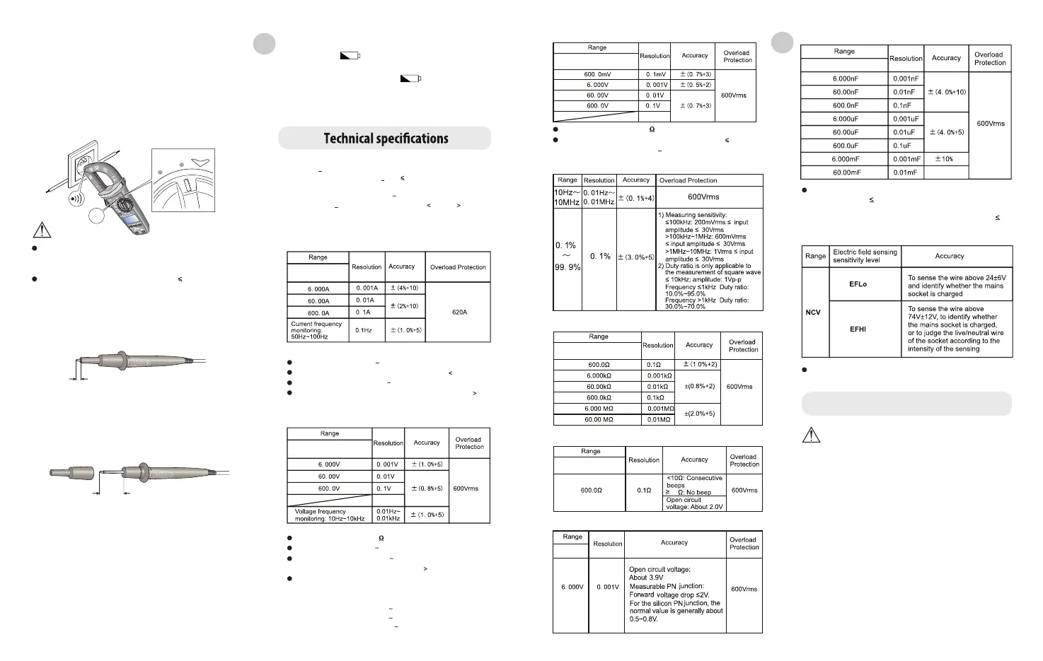
for measurement according to the intensity of the measured electric field.
When the electric field is around 220V (AC) 50Hz/60Hz, select «EFHI»;
when the electric field is around 110V (AC) 50Hz/60Hz, select «EFLo».
TESTING IN CAT III MEASUREMENT LOCATIONS
Picture 5
0.13’’- 0.15’’ (3.3mm - 3.9mm)
NCV
A
EN
Auto power off : during measurement, if there is not operation of the
function switch or any button for 15 minutes, the meter will
automatically shut down to save power. You can wake it up by
pressing any button or restart it after turning the function switch to the
OFF position. to disable the auto power off function, press and hold
the SELECT button in the off state, and then turn on the meter. To
resume the auto power off function, restart the meter after shutdown.
Buzzer : when any button is pressed or the function switch is turned,
if it is valid, the buzzer will make one beep (about 0,5s). When
measuring voltage or current, the buzzer will beep intermittently to
indicate the over range.
s
CAT III shields may be removed for CAT II locations. This will allow
testing on recessed conductors such as standard wall outlets. Take
care not to lose the shields.
TESTING IN CAT II MEASUREMENT LOCATIONS
0.5’’ (13mm)
3 -
Low battery detection : the battery voltage will be automatically
detected as long as the meter is on. If it is lower than 2.5V, the LCD
will display the « » symbol.
4 -
Low battery shutdown function : when the battery voltage is lower
than 2.4V, the LCD display the « » symbol, the «Lo.bt»
interface appears and lasts for about 10s, the buzzer makes
consecutive beeps three times, and then the meter automatically
shuts down (no interface is displayed).
LX-M-2100
LX-M-2100
Accuracy : + (a% of reading + b digits), 1 year calibration period ambient
temperature and humidity : 23°C + 5°C, 80%RH.
Temperature coefficient : to ensure measurement accuracy, operating
temperature should be within 18°C 28°C and the fluctuation range
should be within + 1°C. When the temperature is 18°C or 28°C, add
temperature coefficient error 0.1 x (specified accuracy)/°C.
1 - AC Current
2 - AC Voltage
Frequency response : 50Hz 100Hz
For A4 range, open circuit allows least significant digit 3.
Accuracy guarantee range : 1% 100% of range
The input current amplitude of the current frequency should be 2A.
Input impedance : about 10M
Frequency response ; 45Hz 400Hz, true RMS display
Accuracy guarantee range : 1% 100% of range; the input voltage
amplitude of the voltage frequency should be 5V
The AC crest factor of a non-sinusoidal wave can reach 3.0 at 4000
counts while can only reach 1.8 at 6000 counts. The additional error
should be added for the corresponding crest factor as follows :
a) Add 3% when crest factor is 1 2
b) Add 5% when crest factor is 2 2.5
c) Add 7% when crest factor is 2.5 3
LX-M-2100
3 - DC Voltage
Input impedance : about 10M
For mV range, short circuit allows least significant digit 5.
Accuracy guarantee range : 1% 100% of range
LX-M-2100
LX-M-2100
4 - Frequency/Duty Ratio
5 - Resistance
6 - Continuity
LX-M-2100
7 - Diode
LX-M-2100
9 - NCV
8 - Capacitance
Maintenance
Measured value = displayed value - open circuit value of the test leads
(For capacitance 100nF, it is recommanded to use «REL»
measurement mode.)
For capacitance range, open circuit allows least significant digit 20.
Test results may be affected by different socket designs or wire
insulation thickness.
Warning :
Before opening the rear cover of meter, remove the test leads
to avoid electric shock.
EN
1 - General Maintenance
2 - Battery replacement (picture 7)
1 -
When the meter is not in use, place the function switch in the OFF
position to avoid continuous consumption of battery energy.
2 -
Clean the meter casing with a soft cloth and mild detergent.
Do not use abrasives or solvents!
3 -
The maintenance and service must be implemented by qualified
professionals or designated departments.
1 -
Turn off the meter and remove the test leads from the input terminals.
2 -
Unscrew the screw of the battery compartment, remove the battery
cover, and replace the 2 standards AAA batteries according to the
polarity indication.
3 -
Secure the battery cover and tighten the screw.
50
 Loading...