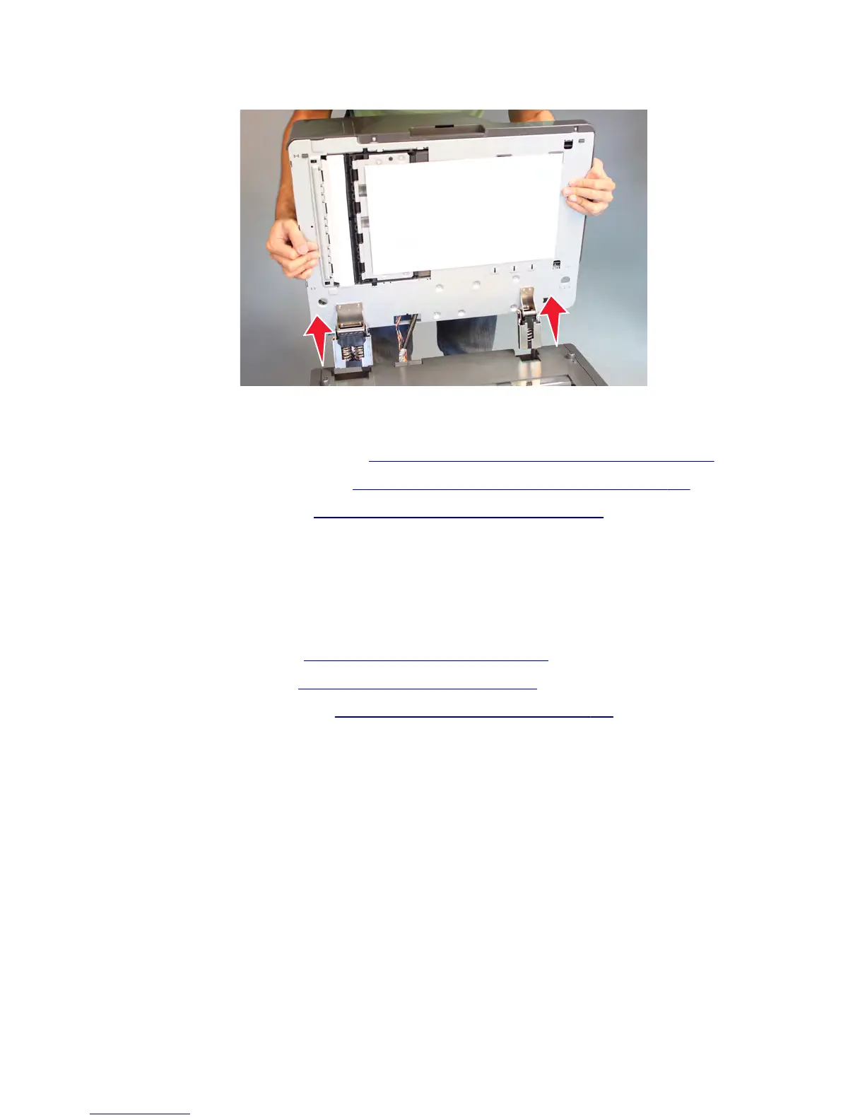
5 Open the ADF, and then lift to detach the ADF from the flatbed scanner.
Installation note: Make sure to perform the following scanner calibration procedure after replacing the ADF
assembly:
1 Regenerate high frequency defect data. See “Regenerating high frequency defect data” on page 405.
2 Register the front ADF and back ADF. See “Registering the front ADF and back ADF” on page 406.
3 Retune the ADF magnification. See “Retuning the ADF magnification” on page 412.
Installation note: When installing this part, check the firmware version installed in the printer. If the version
installed is P132 and E215 or higher, then no further action is needed. If the version installed is lower than P132 and
E215, then update the firmware to the latest version to maintain proper printer operation.
ADF bottom door removal
1 Remove the ADF front cover. See “ADF front cover removal” on page 587.
2 Remove the ADF rear cover. See “ADF rear cover removal” on page 598.
3 Remove the flatbed glass cushion. See “Flatbed glass cushion removal” on page 632.
4 Disconnect the JBCON1 connector on the ADF controller card.
7463
Repair information
577
 Loading...