Interfaces
8-14
• Controls data flow control with BUSY and ACKNLG* signals. Does not carry
out data transfer by ignoring the BUSY or ACKNLG* signal. (The system can
carry out data transfer to the printer only when the level of the BUSY signal is
low and after confirming the ACKNLG* signal is high.)
• Uses standard transistor-transistor logic (TTL) levels for all interface control
signals and input data. Interface conditions are based on TTL levels. All
printer outputs are totem-pole TTL devices. All printer input/output (I/O) are
devices with an internal pull-up resistor to 5 V. Rise and fall times of each
signal must be less than 1,500 nanoseconds (ns) without slope reversal.
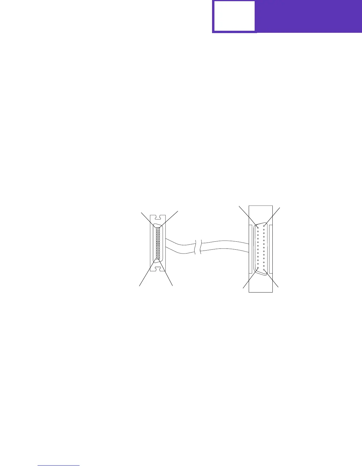
Optional Parallel Connector
The cabling in the following illustration supports Standard and Fastbytes protocols and
IEEE 1284 Nibble, Byte, and ECP protocols.
18
36
1
19
14
1
25
13
Printer
Side
36-Pin
D-Shell
Connector
(Male)
Computer
Side
25-Pin
D-Shell
Connector
(Male)
IEEE 1284-A
IEEE 1284-C
 Loading...