Maintenance
3.6.6 Cleaning the Parts and Checking for
Wear
Inspect all surfaces for scratches, marks, running-in
tracks or other damage. If possible, carefully smooth the
surfaces with emery paper.
If the parts are considerably damaged,
especially sealing surfaces or keyways,
replace them. In the case of seals and O-
rings always use new parts.
Using suitable wires, ensure that all oil channels are
clear of dirt. Blow compressed air through the channels
and clean all parts with a suitable solvent and then dry
them thoroughly with compressed air.
Check that all keys are clean and fit snug in their
keyways and that the cams and the ring gear can be pus-
hed without difficulty onto the shaft with its keys.If neces-
sary, rub the parts with emery paper and then clean
them again.
Unscrew and clean the gas ballast valve. All parts, inclu-
ding gaskets and O-rings needed for assembly, should
be moistened with pump oil.
3.6.7 Reassembling the Pump
Reassemble the pump in the reverse sequence.
Observe the following:
Inserting the intermediate plate
When pulling the intermediate plate (12/2) back in (spe-
cial tool 8), ensure that the O-ring (12/3) is not damaged.
Counterbalancing
When installing the ring gear and cams, make sure that
the cams and ring-gear counterbalance are fitted alter-
nately at the top and bottom so that the pump remains
counterbalanced (see Fig. 3).
Inserting the radial shaft seal
Using a suitable tool, force in the radial shaft seal from
the interior side of the front end plate (for position of radi-
al shaft seal, see Fig. 12).
Selecting the shims
One or more shims (9/23) have to be inserted between
the ball bearing (9/24) and the outer race (9/20). To
determine the correct thickness, proceed as follows:
As a trial, mount one or more 1 mm thick shims.
Attach the outer race, but tighten the screws only by
hand.
Using a thickness gauge, measure the gap between the
front end plate and outer race.
The correct thickness of the shims is obtained as follows:
1.00 mm minus gap measured plus 0.10 mm
Remove the 1 mm thick shims mounted for trial purposes
and insert shims of the thickness calculated.
Example: Gap measured is 0.70 mm
Thickness of shim(s) required:
1.00 mm - 0.70 mm + 0.10 mm = 0.40 mm
22
GA 02.200/8.02 - 10/02
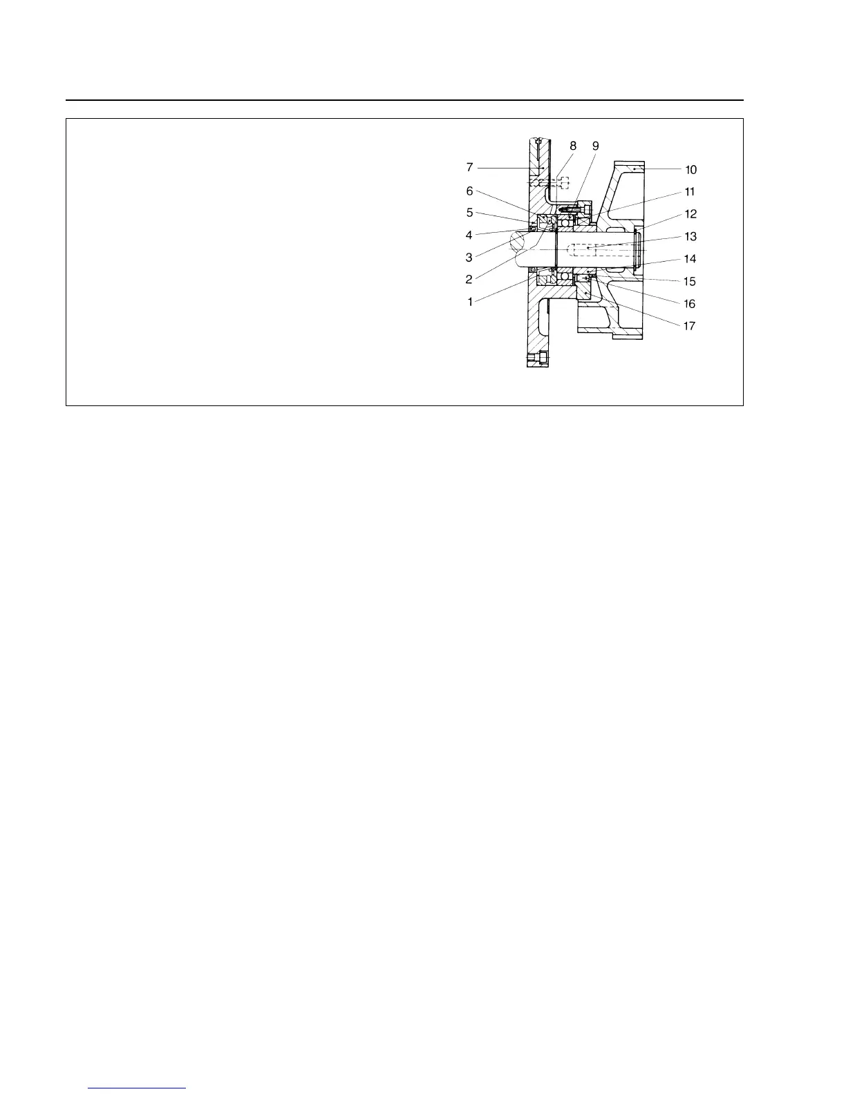
Key to Fig. 12
1 L-ring shaft seal (8/27)
2 Oil flow holes
3 Circular spring on ID of radial shaft seal
4 Radial shaft seal (8/7)
5 Bottom surface of bearing well
6 Spacer (8/26)
7 Front end plate (8/8)
8 Retainer ring (8/25)
9 Bearing (8/24)
10 Ring gear (8/18)
11 Shims (8/23)
12 Retainer ring (8/17)
13 Key
14 Inner race (8/22)
15 Spacer (8/19)
16 Reverse lock (8/21)
17 Outer race (8/20)
Fig. 12 Cross-section of the bearing in the motor lid (see also Fig. 9)
Caution