GA 02.200/8.02 - 10/02
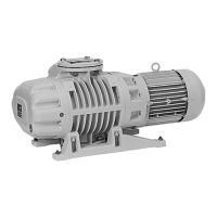
1.1.2 Design
The E-250 has three pumping chambers operating in
parallel.
The DK-200 has three, pumping chambers operating in
series, with the larger chamber(s) on the intake side
acting as the first pump stage, and the smaller chamber
as the second pump stage.
Above the exhaust valves (2/5) is an oil reservoir, from
which oil is injected into the pumping chamber via oil
channels (2/4).
The oil is used for sealing, lubrication and cooling. Most
of the oil entrained with the compressed gas is mechani-
cally trapped in the exhaust box (2/7). The oil cycle is
maintained by the difference between the pump's intake
pressure and atmospheric pressure.
The rotary piston pumps are driven by a directly flanged
motor. The pump's rotational speed is lower than that of
the motor; the pump shaft and motor are interlinked by a
toothed gear, which has its own oil reservoir.
The cams (2/2) or (3/1) and (3/11) and a ring gear are
arranged on the pump shaft in such a way that the
eccentrically rotating array is dynamically balanced.
The pumps are air-cooled. The required air flow is gene-
rated by the attached motor. A built-in reverse lock pre-
vents the motor turning the pump shaft in the wrong
direction.
All E and DK series pumps have a gas ballast device.
When the gas ballast valve (2/8) is open, a dosed quan-
tity of air – so-called "gas ballast" – is admitted into the
pumping chamber.
Description
This prevents condensation of vapours in the pump up to
the vapour tolerance specified in the Technical Data.
In addition, a small amount of air is constantly admitted
via the silencer nozzles so as to avoid loud running of the
pump at ultimate pressure.
1.2 Supplied Equipment
The pumps are supplied with small-flange (KF) and/or
clamp-flange (ISO-K) connections (see Section 1.3 –
Technical Data).
For each small-flange connection, a centering ring and a
clamp ring are supplied. These connections are sealed
with a rubber diaphragm.
For each clamp-flange connection, a sealing disk with
collar flange and snap ring is supplied. These connec-
tions are sealed with cardboard disks.
The centering ring or sealing disk for the inlet flange con-
tains a dirt trap.
The pump and gear housing are filled with N 62 oil.
4
Key to Fig. 2
1 Piston
2 Cam
3 Drive shaft
4 Oil channel
5 Exhaust valve
6 Oil-level glass
7 Exhaust box
8 Gas ballast activator
9 Dirt trap
10 Inlet port
11 Piston neck
12 Slide valve
13 Cooling fins
14 Pump body
Fig. 2 Cross-section of rotary piston pump and principle of operation