300781309_002_C0 - 01/2019 - © Leybold 8
Part name and component function
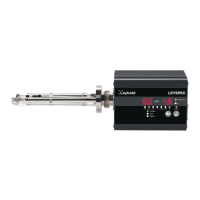
2.2 Rear panel
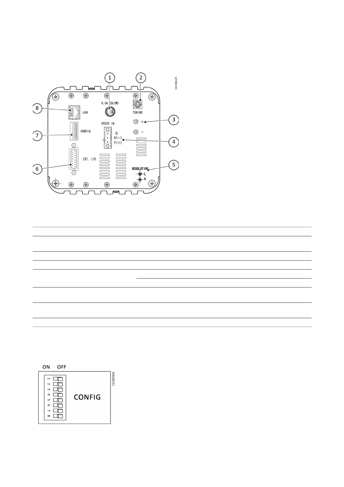
2.3 DIP switch
Set up the DIP switch numbers 1, 3, and 4 through 8 with the power supply OFF.
Item Name Function
1 Power fuse holder (FUSE) Over-current protection (Time lag type 6.3 A).
2 Rotary switch for regulating tuning
voltage (TUNING)
Regulates RF voltage tuning with the analyzer tube.
3 Tuning voltage check terminal (+, -) Terminal for checking RF voltage tuning with the analyzer tube.
4 Power inlet connector (POWER IN) Power cable connector (includes ground).
5 Resolution adjustment
potentiometer (RESOLUTION L, H)
L: Adjusts the resolution of the low mass number.
H: Adjusts the resolution of the high mass number.
6 External input/output connector
(EXT-I/O)
Signal I/O connector (D-sub 15-pin male).
7 Initial setting DIP switch (CONFIG) DIP switch for SEM selection, IP address setting, the unit address setting and
local/remote selection.
8 Ethernet connector (LAN) RJ45 connector (8-pole 8-wire) for connecting the LAN cable
 Loading...