GA 05.218/3.02 - 11/97
Connection
10
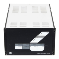
Key to fig. 5
1 Power switch
2 Relay contact for forevacuum
pump ON/OFF
3 Connection for supply of the
TURBOVAC
4 LED red, magnetic bearing
active
5 Connection for the magnetic
bearing of the TURBOVAC
6 Connection socket for RS 232
interface
7 Connection terminal strip
8 Potentiometer for setting
the delay time
9 Parameter selection for RS 232
interface
10 Connection for voltage supply of
the temperature controller
11 Connection for cooling water
magnetic valve
12 Connection for heating collar
13 Connection for forevacuum valve
14 Connection for Pt 100
15 Connection of the power linecord
Fig. 5 TURBOTRONIK NT 340 MA with temperature control unit, rear panel
Warning
Prior to opening the temperature control unit
pull it off. If the plug of the temperature control
unit is connected there may be line voltage
inside the unit.
Fig. 6 Location of the fuses F1, F2, F3 in the temperature control unit;
bottom removed
Table 3: Temperature Control Unit: Pin assignment of the Sub D Sockets
Sub D Socket VOLTAGE I/0 (Plug) Sub D Socket Pt 100 (Socket)
Pin 1 Relay contact* Linked with pin 2
Pin 2 Voltage of the Pt 100 (0.1 V corresponds to 1 °C) Pt 100
Pin 3 Common point for the relay* Pt 100
Pin 4 Voltage treshold „NORMAL“ Linked with pin 3
Pin 5 Relay contact* Linked with pin 3
Pin 6 Earthed (of NT: pin 21 of the socket REMOTE) Linked with pin 2
Pin 7 Voltage treshold „Pump too cold“ Linked with pin 3
Pin 8 Voltage treshold „Pump too hot“ Linked with pin 3
Pin 9 + 15 V (of NT: pin 210 of the socket REMOTE) Linked with pin 3
Voltage supply for temperature controller
* If the pump is too hot or too cold (FAILURE), the contact between pin 1 and 3 is closed and open between pin 3 and 5.
In the operation mode NORMAL of the temperature controller the contact between pin 1 and 3 is open and closed between pin 3 and 5.
Too hot: T > 75 °C (167°F); too cold: T < 55 °C (131°F); NORMAL: 55 °C ≤ T ≤ 75 °C (131°F ≤ T ≤ 167°F)
 Loading...