GA 05.218/3.02 - 11/97
Connection
7
2 Connection
Warning
Connections for forevacuum pump, cooling,
venting valve and flange heater must be
done by a qualified electrician in accord-
ance with the applicable safety regulations.
2.1 Setting the Mains
Voltage
The TURBOTRONIK has been set at the factory for a
mains power supply; see Section „1.2 Standard Specifi-
cation“.
To change this setting, remove the dummy plug (3/15)
with a screwdriver and reinsert it according to the stam-
ped-on voltage setting. The selected voltage indication
must be in the immediate proximity of the arrow.
If you do change the voltage setting, please also change
the line power fuse accordingly; see the table.
Fuses
LINE VALVE HEATING FAN
————————————————————————
100 V T*) 4.0 A T 0.315 A T 3.15 A T 1.0 A
120 V T 8.0 A T 0.315 A T 3.15 A T 1.0 A
220/240 V T 4.0 A T 0.315 A T 3.15 A T 1.0 A
(*) slow-blow)
In case of need, other fuses may be installed for VALVE,
HEATING and FAN. However, the sum of the fuses’
capacity for the three connections must not exceed:
4.5 A for 100/120 V
6.0 A for 220/240 V.
Plug the power linecord into the socket (3/14), (5/15).
The NT 341 MT has a fixed linecord.
2.2 Connecting the
TURBOVAC
Insert and fasten the connection line to the motor of the
TURBOVAC at the socket DRIVE and to the TURBOVAC
itself.
Insert and fasten the connection line to the stabilizer and
axial sensor of the TURBOVAC at the socket BEARING
and to the TURBOVAC itself; both plugs are non-inter-
changeable.
2.3 Connecting the
Forevacuum Pump
Connect the forepump to the relay contact output FORE-
PUMP. When pressing the START key the contact is
closed without any delay and the forepump is switched
on.
The forepump is shut down when the TURBOVAC has
come to a standstill, switching examples see fig. 11.
A starting delay for the TURBOVAC can be set at the
potentiometer DELAY; see Section 3.1
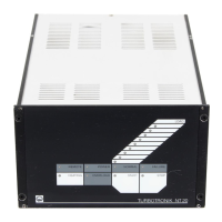
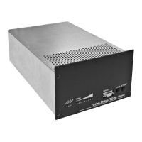
NT 340 MA with
plugged-in temperature
control unit
(Front panel)
(Housing)
Fig. 2b Dimensional drawings of TURBOTRONIK , dimensions in mm
 Loading...