3 Maintenance
3.1 LEYBOLD Service
If equipment is returned to LEYBOLD, indicate whether
the equipment free of substances damaging to health or
whether it is contaminated. If it is contaminated also indi-
cate the nature of the hazard. For this you must use a
form which has been prepared by us which we will pro-
vide upon request or you may copy the from which has
been reproduced on the next to the last page of this
handbook.
Please attach this form to the equipment or enclose it
with the equipment.
This „Declaration of Contamination“ is required to meet
German Law and to protect our personnel. Leybold must
return any equipment without a „Declaration of Contami-
nation“ to the sender’s address.
Before shipping, fit the yellow screw-on seals on to the
connections EXHAUST (3/5) and GAS BALLAST (3/6)
(see Chapter 2.1.2).
3.2 Maintenance Plan
Maintenance work should be done on the UL 200 as
required.This work will normally be limited to exchanging
the oil in the D 2,5 E rotary vane pump and the built-in
air filters.
As a preventive measure it is recommended that you
check the rotary vane pump once a month. Here note
should be taken of the oil level and the colour of the oil.
For details on this please refer to the Operating Instruc-
tions GA 01.600 for the TRIVAC D 2,5 E which have
been enclosed.
Caution Only Arctic oil (Cat. No. 200 28 191)
must be used in the TRIVAC D 2,5 E in
the UL 200.
The monthly interval for the check is just a nominal peri-
od. If the leak detector is used heavily, in particular in the
sniffer mode, then this check should be performed more
frequently. The rotary vane pump is located on the side
of the mechanical section at the bottom of the leak
detector.
3.2.1 Opening the UL 200
Switch the UL 200 off.
Pull the mains cord on the UL 200.
Remove the cover (6/8) for the mechanical section.
Separate the UL 200 from other vacuum components at
the test port (6/2).
Turn the UL 200 so that it is orientated in the same way
as shown in Fig. 6.
31
TH 10.211/8.02 - 12/97
4
5
6
7
8
9
1
10
2
3
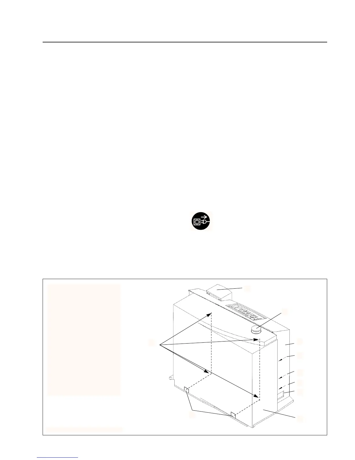
Key to Fig. 6
1 Hand unit
2 Test port
3 Cover for the electronics section
4 VENT input
5 Connection for the exhaust line
6 Gas ballast connection
7 Mains switch with mains fuses
8 Cover for the mechanical section
9 Openings for removal of the
cover for the mechanical section
10 Four screws for loosening the
cover for the electronics section
Fig. 6 View of the mechanical side