these must be followed closely.
As already stated in Chapter 3.2 only Arctic oil must be
used for the D 2,5 E pump in the UL 200.
Fit the cover for the mechanical section (6/8).
3.2.4 Cleaning
The housing of the UL 200 is made of painted plastic
parts.Thus for the purpose of cleaning, only such agents
should be used which are generally also used for other
pained or plastic surfaces (mild household cleaning
agents, for example). Normally a moistened piece of
cloth will do. Never use any solvents which are capable
of dissolving paint (like acetone, toluol, etc.).
A soft brush or a vacuum cleaner is recommended for
cleaning the ventilation slits.
3.2.5 Exchanging the Fuses
Warning Before exchanging the fuses you must
disconnect the mains cord.
Switch the UL 200 off.
Pull the mains cord on the UL 200.
Use a screwdriver to fold out the lid of the mains socket
(3/7) from the right (the mains switch is not affected by
this).
The fuses can be removed by pulling the drawers out
which are marked by the arrows.When reinserting these
make sure that the arrows point downwards.
In any case two fuses of the same rating must be inser-
ted. The required mains fuses are:
- T 3.15 A slow-blow (20 x 5 mm dia.) for the 230 V
model.
- T 6.3 A slow-blow (20 x 5 mm dia.) for the 100 / 110 V
model.
After having exchanged the fuse(s) press the lid of the
mains socket firmly back on.
Insert the mains cord into the UL 200 and switch the
instrument on.
Besides these mains fuses several internal circuits are
fused separately. These fuses are listed in the following
table. See also Fig. 8.
In order to exchange these fuses you must proceed as
follows:
- Switch the UL 200 off.
- Pull the mains cord on the UL 200.
- Remove the cover for the mechanical section (6/8) and
the cover for the electronics section (6/3) according to
Chapter 3.2.1.
33
TH 10.211/8.02 - 12/97
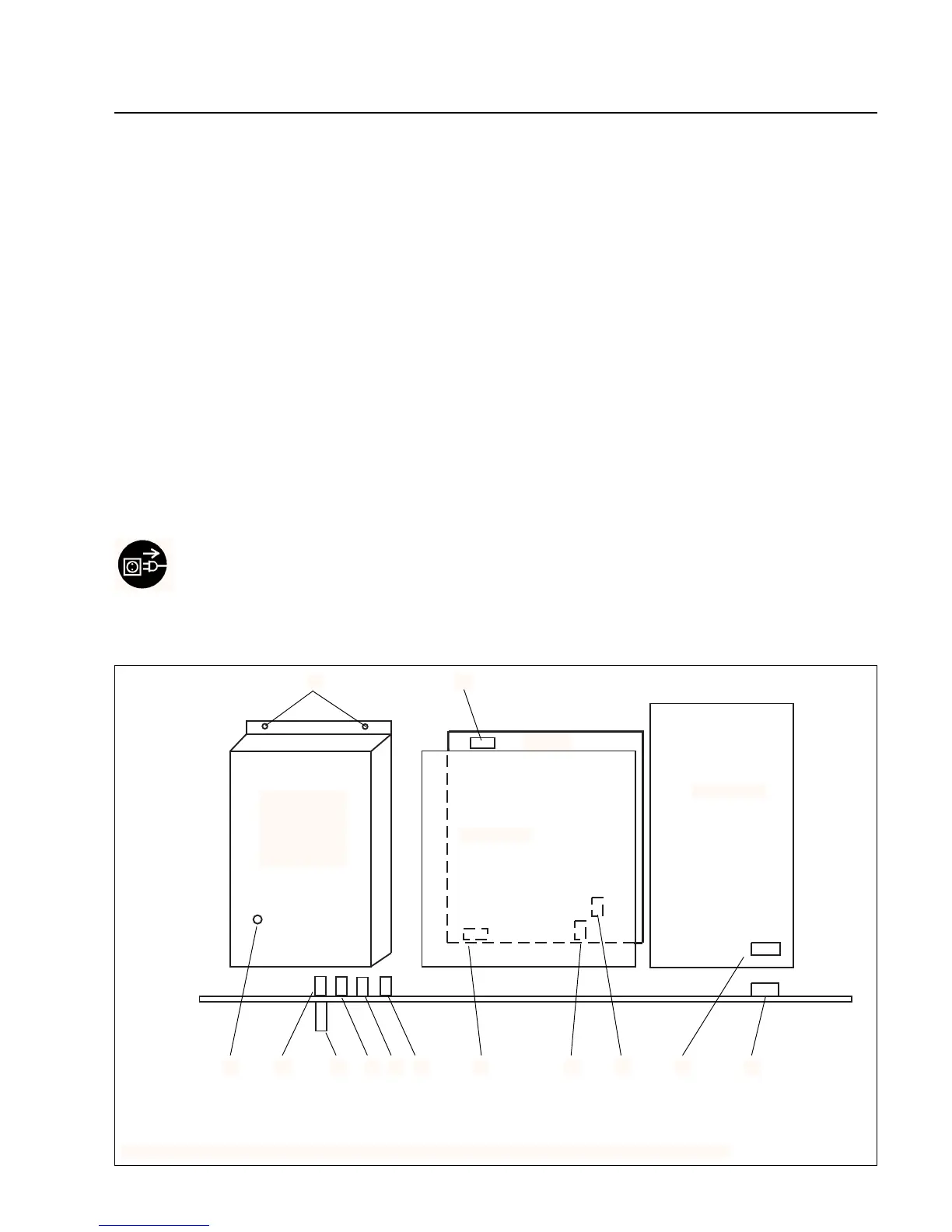
Fig. 8 Arrangement of the printed circuit boards and the fuses on the electronics side (top view)
TMP conver-
ter NT 12
MSV
STE board
I / O board
1 3 4 5 6 7 10
11
982
VD
Wiring back plane
12
13