41
August 2010 42PJ350 Plasma
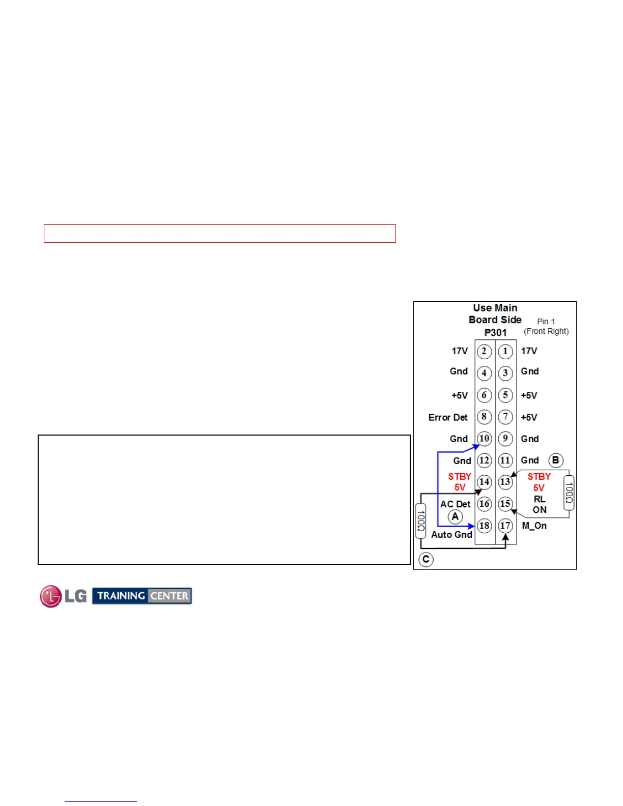
(A) Ground the Auto Gnd Line (Pin 18) will allow the supply to be
powered up one section at a time.
(B) Add a 100Ω ¼ watt resistor from 5V Standby to RL_ON and the 17V
and 5V Run Lines on P813 will become active. Also AC-Det and
Error_Det will go high.
(C) Add a 100Ω ¼ watt resistor from any 5V line to M_ON (Monitor On) to
make the M5V, VS and VA lines operational.
P811 (VS pins 1 and 2) (VA pins 6 and 7) and the (M5V pins 9 and 10).
TEST CONDITIONS:
Connector going to the Y-SUS P811 is disconnected.
P301 on the Main board disconnected (coming in on P813).
Use the holes on the connector P301 (Main Board side) to insert the resistors or jumper leads.
Connect (2) 100 Watt light bulbs in series between VS and Ground.
WARNING: Remove AC when adding or removing any plug or resistor.
Power Supply Static Test (Forcing on the SMPS in stages)
Power Supply Static Test (Forcing on the SMPS in stages)
When the supply is operational in its normal state the Auto Ground line at Pin
18 of P813 is held at ground by the Main Board.
This Power Supply can be powered on sequentially to test the Controller
Chip IC701 operational capabilities and for troubleshooting purposes.
By disconnecting P301, pin 18 is opened. To return the SMPS to the normal
state for this test procedure, this pin must be grounded.
(See first step A below).
Note: Leave previous installed 100Ω resistor in place
when adding the next resistor.

 Loading...