- 116 -
Copyright ©2007 LG Electronics. Inc. All right reserved.
Only for training and service purposes
LGE Internal Use Only
Control Devices and Function
• Function of LG Network
- It is possible to connect the network of LG air conditioners and to connect various contents of the network
system, which is simple, deluxe and PC central control.
- Please refer to "LG Control System Manual" about the detail functions and the products possible to network.
- As the Interface for networking, PNF-P14A0M/R/C is applied.
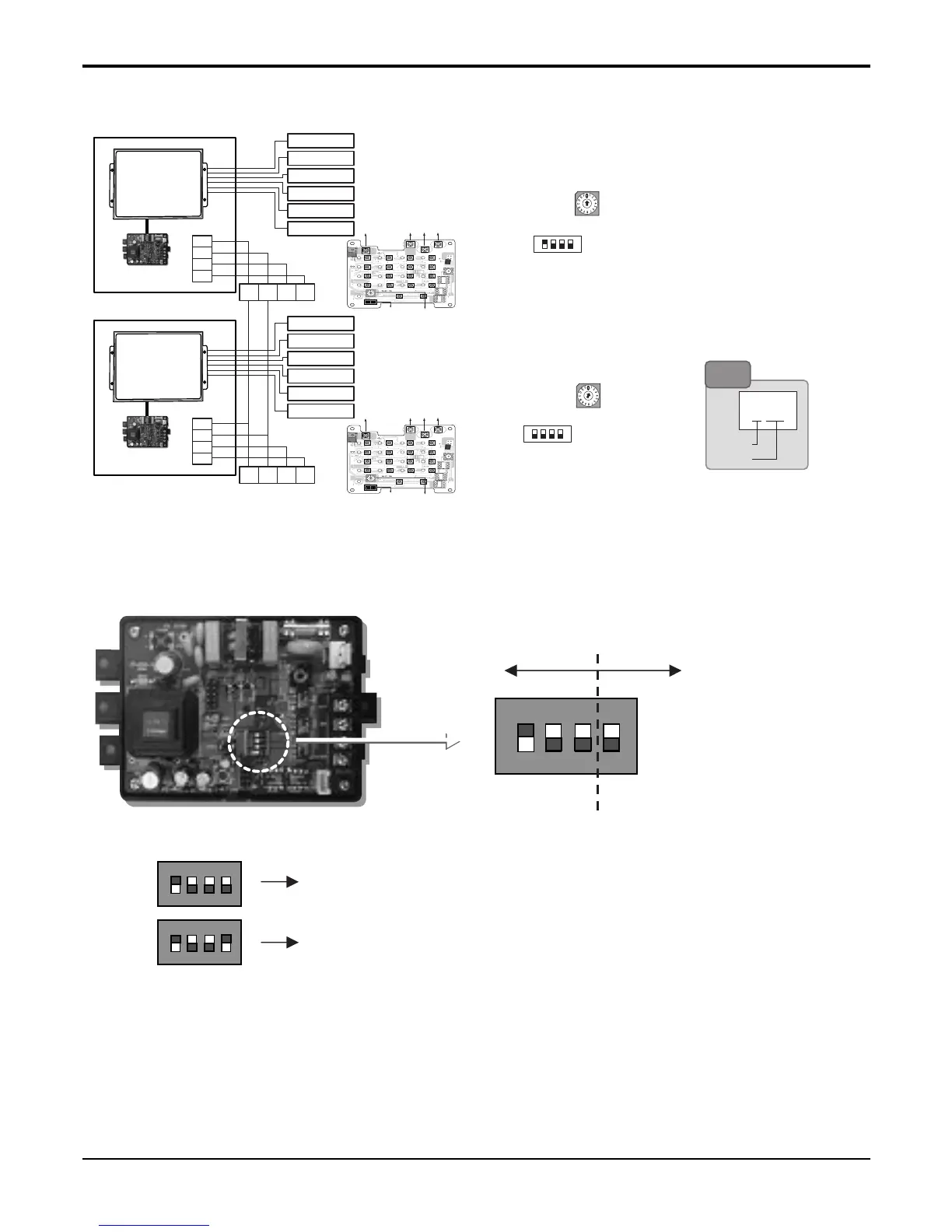
PI485 setting method(LG Aircon Network unit)
■ 2 OR MORE SIMPLE CENTRAL CONTROL CONNECTION
ON
L1 2 3 4
KS DO 4H
ON
L1 2 3 4
KS DO 4H
■ Settings method of TPS Inverter Multi Type
1,4
1 ON + All OFF : Connection of "TPS Inverter Multi Connection + General Central
Controller" Case.
ON + All OFF : Connection of "TPS Inverter Multi Connection +
Central Controller applied 「LGAP」" Case.
* LGAP : LG Air conditioners Protocol
ON
L1 2 3 4
KS DO 4H
Selection of product
unit type
Selection of network type
<Group Number 0>
Master
DIP SWITCH
<Group Number 1>
001
Group No.
Indoor No.
Note
1. Adhere the PI485 Module(For connecting central control) to the Control Box.
2. Connect the PI485 Module to central control.
3. In the case of connecting two more than central control, set the Master/Slave mode
and then connect each communication lines(C,D) <Refer to above fig>.
*Special purcharse: Central control(P/No.:4995A20105F),
PI485 Module(PNF-P14A0M)
* It can be added to 15 Central controls for the slave control.
Slave
DIP SWITCH
Group Number 0
Master Mode
Vcc
GND
C
D
CN-POWER
GND
CN-COM A
S4
S3
S12
S16
TX1
LED4
LED8
LED12
LED11
LED16
LED15
PWB:6870A10001A
ASM:6711A20005E
LED7
LED3
L
+
+
+
+
+
+
+
+
+
S15
S18
S19
S15
S11
S2
LED2
S5
S9
+
+
S1
IC1P
LED5
LED9
LED13
LED17
LED10
LED14
S14
+
S6
S10
CN-POWER
CN-COM B
ON
L1 2 3 4
KSDO4H
OUTDOOR
MAIN PCB
INDOOR UNIT 1
INDOOR UNIT 2
INDOOR UNIT 3
INDOOR UNIT 4
INDOOR UNIT 5
INDOOR UNIT 6
Outdoor unit 1
BUS
B
D C GND VCC
BUS
A
GND
+10V
OUTDOOR
MAIN PCB
INDOOR UNIT 1
INDOOR UNIT 2
INDOOR UNIT 3
INDOOR UNIT 4
INDOOR UNIT 5
INDOOR UNIT 6
Outdoor unit 2
BUS
B
D C GND VCC
BUS
A
GND
+10V
 Loading...