GUIDELINES | 75
Application Guidelines
'XHWRRXUSROLF\RIFRQWLQXRXVSURGXFWLQQRYDWLRQVRPHVSHFL¿FDWLRQVPD\FKDQJHZLWKRXWQRWL¿FDWLRQ
©
/*(OHFWURQLFV86$,QF(QJOHZRRG&OLIIV1-$OOULJKWVUHVHUYHG³/*´LVDUHJLVWHUHGWUDGHPDUNRI/*&RUS
Wired Controller Placement
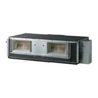
Gallery and Wall-mounted indoor units can be used with various wired controllers
(optional; sold separately). Wired controllers include a sensor to detect room tem-
perature. To maintain comfort levels in the conditioned space, the wired controller
must be installed in a location away from direct sunlight, high humidity, and where it
could be directly exposed to cold air. Controller must be installed four (4) to five (5)
feet above the floor where its LED display can be read easily, in an area with good
air circulation, and where it can detect an average room temperature.
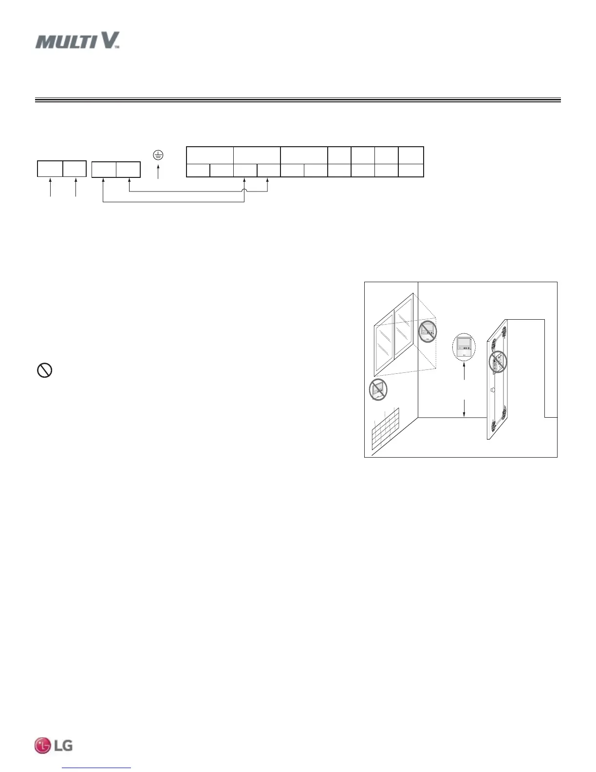
Do not install the wired controller near or in:
• Drafts or dead spots behind doors and in corners
• Hot or cold air from ducts
• Radiant heat from the sun or appliances
• Concealed pipes and chimneys
• An area where temperatures are uncontrolled, such as an outside wall
Figure 68: Proper Location for the Wired Controller.
4 to 5 feet
above the floor
NO
NO
NO
YES
Remote Controlle r
TEMP
Remote Controlle r
TEMP
R
e
m
o
t
e
C
o
n
t
r
o
l
l
e
r
TE
M
P
:LULQJ*XLGHOLQHV
APPLICATION GUIDELINES
Figure 69: 6LPSOL¿HG9LHZRI,QGRRU8QLW7HUPLQDO&RQQHFWLRQV²69:DOO0RXQWHG)UDPHV
Indoor Unit Terminal Block
L(L1)
Power Input
208-230V /
60 Hz / 1 Phase
A-- ----ABB
GND 12V
DRY2DRY1
INTERNETIDUSODU
Ground
3(A) 4(B)
N(L2)
Outdoor Unit Terminal Block
To Outdoor Unit



 To Next Page