35
Installation
Due to our policy of continuous product innovation, some specications may change without notication.
©LG Electronics U.S.A., Inc., Englewood Cliffs, NJ. All rights reserved. “LG” is a registered trademark of LG Corp.
Installing and Setting Outdoor Units in Dual / Triple Frame Systems
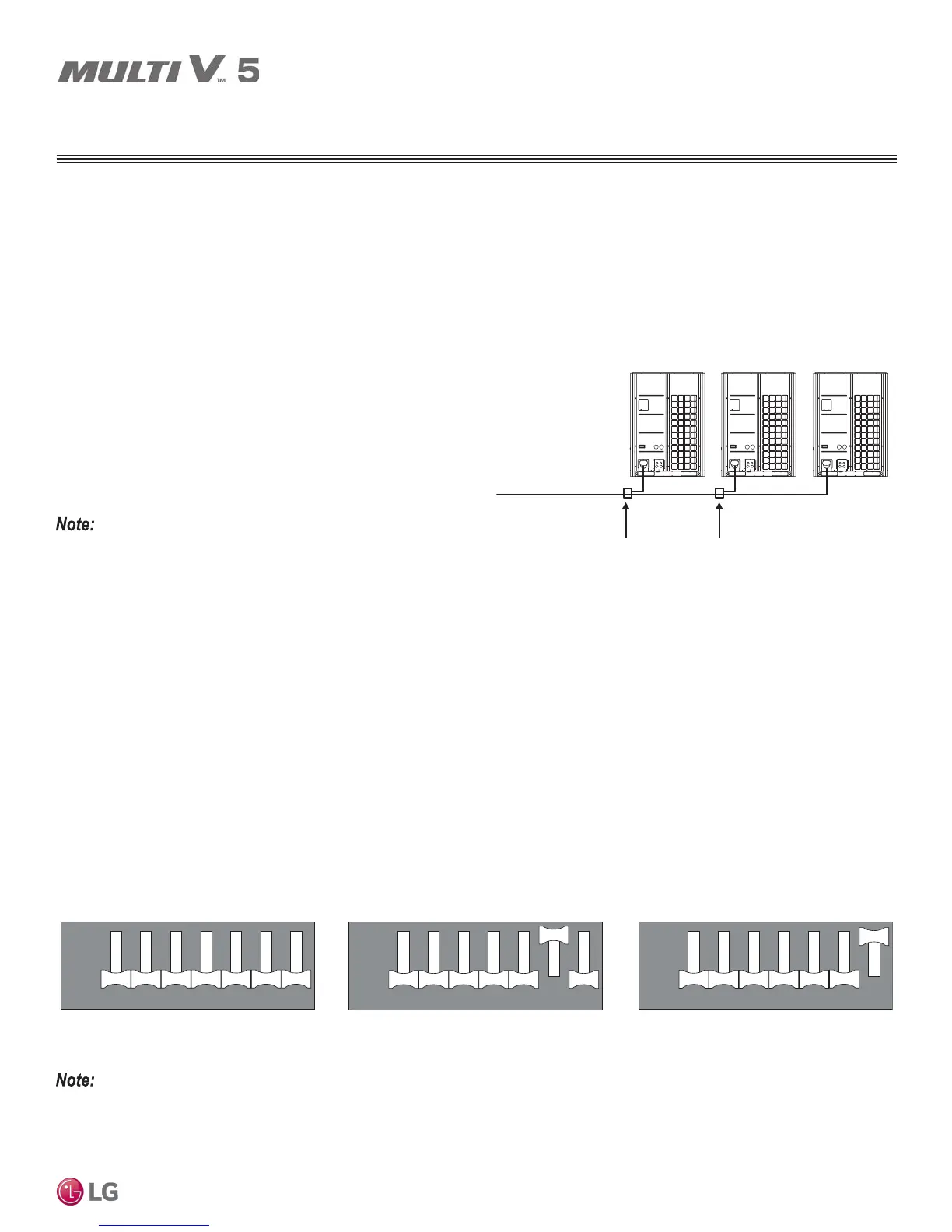
To ensure proper system operation, the individual outdoor units within dual and triple frame systems must be physically installed in a certain
order, and DIP switches must be appropriately set.
Installing Outdoor Units in Dual / Triple Frame Systems
• The master unit must always be the largest capacity outdoor unit in
a dual or triple frame system.
• The master unit must always be placed the closest to the indoor
unit / heat recovery unit refrigerant piping system.
• The slave1 unit must always be the next largest capacity outdoor
unit in a dual or triple frame system, and must be larger than the
slave 2 unit.
• The slave 2 unit must be the smallest capacity outdoor unit in a
triple frame system.
PLACEMENT CONSIDERATIONS
See also the DIP Switch Settings in the Pre-Commissioning section.
Installing and Setting Outdoor Units in Dual / Triple Frame Systems
12 76543
12 76543
ON
OFF
12 76543
12 76543
ON
OFF
12 76543
12 76543
ON
OFF
Master Outdoor Unit Slave1 Outdoor Unit Slave2 Outdoor Unit
A ≥ B ≥ C
Master Outdoor Unit to
Slave1 Outdoor Unit
Connection Piping
(First Y-Branch)
(Master)
AB
(Slave 1)
C
(Slave 2)
Piping to Indoor Units
/ Heat Recovery Units
Slave1 Outdoor Unit to
Slave2 Outdoor Unit
Connection Piping
(Second Y-Branch)
Installing Outdoor Units In Dual / Triple Frame Systems.
Setting Outdoor Units in Dual / Triple Frame Systems
On the DIP-SW01 bank (Main PCB), one (1) outdoor unit must be set on DIP-SW01 bank to the Master unit and the other units set to the
Slave(s) unit(s) or errors will be generated.
• For the DIP-SW01 bank on the master unit, all DIP switches must be set to OFF.
• For the DIP-SW01 bank on the slave 1 unit, set only DIP switch 6 to ON.
• For the DIP-SW01 bank on the slave 2 unit, set only DIP switch 7 to ON.
Master, Slave1, and Slave2 DIP Switch Settings.
Oil traps may need to be installed in scenarios where the dual-frame or
triple-frame outdoor units are separated (requirement is based on dis-
tance between the units). For detailed information, see the “Refrigerant
Piping for Separated Outdoor Units” section.



 To Next Page