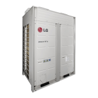
Front Side 1 Front Side 2
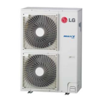
Main Power Connection Communication Connection
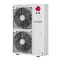
Checking the setting of outdoor units
Checking according to dip switch setting
- You can check the setting values of the Master outdoor unit from the
7 segment LED.
The dip switch setting should be changed when the power is OFF.
Checking the initial display
The number is sequentially appeared at the 7 segment in 5 seconds
after applying the power. This number represents the setting condition.
• Initial display order
• Example) ARUN620LTE4
• Master Unit • Slave Unit
Dip switch setting Dip switch setting ODU Setting
Slave 1
Slave 2
Slave 3
Order No Mean
①
8~20 Master model capacity
②
10~20 Slave 1 model capacity
③
10~20 Slave 2 model capacity
④
10~20 Slave 3 model capacity
⑤
8~80 Total capacity
⑥
1 Cooling Only
2 Heat Pump
3 Heat Recovery
⑦
38 380V model
46 460V model
22 220V model
⑧
1 LTE4
2 LTS4
① ② ③ ④ ⑤ ⑥ ⑦ ⑧
18 16 14 14 62 2 38 1
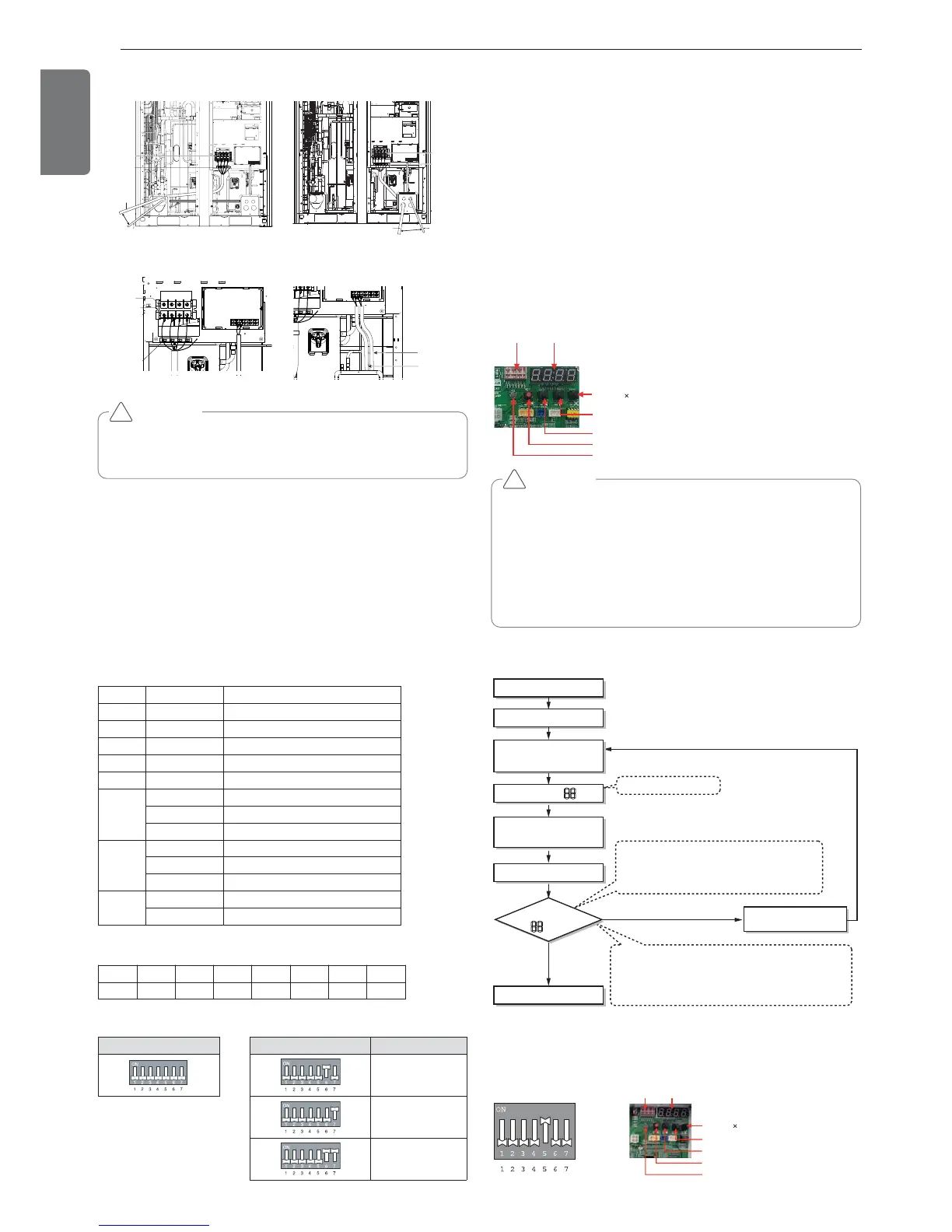
Automatic Addressing
The address of indoor units would be set by Automatic Addressing
- Wait for 3 minutes after supplying power.
(Master and Slave outdoor units, indoor units)
- Press RED button of the outdoor units for 5 seconds. (SW01C)
- A “88” is indicated on 7-segment LED of the outdoor unit PCB.
- For completing addressing, 2~7 minutes are required depending on
numbers of connected indoor units
-
Numbers of connected indoor units whose addressing is completed are
indicated for 30 seconds on 7-segment LED of the outdoor unit PCB
- After completing addressing, address of each indoor unit is indicated
on the wired remote control display window. (CH01, CH02,
CH03, ……, CH06 : Indicated as numbers of connected indoor units)
[Heat Pump (MAIN PCB)]
CAUTION
• In replacement of the indoor unit PCB, always perform Automatic
addressing setting again (At that time, please check about using
Independent power module to any indoor unit.)
• If power supply is not applied to the indoor unit, operation error
occur.
• Automatic Addressing is only possible on the master Unit.
• Automatic Addressing has to be performed after 3 minutes to im-
prove communication.
!
The Procedure of Automatic Addressing
• Automatic addressing setting end
Numbers of indoor unit connection set whose
addressing is completed are indicated for 30seconds
on 7-segment LED after completing setting
Indoor address number is displayed on wired remote control or
indoor unit display window. It is not an error message, will
disappeared when on/off button is pressed on remote control
ex) Display of 01, 02, ..., 15 means connection of 15 indoor units
and Automatic addressing is completed normally.
Automatic addressing start
Waiting 3 minutes
Power On
Press RED Button for 5 sec.
(SW01C)
7-segment LED = 88
Don’t press RED Button
(SW01C)
Waiting about 2~7 minutes
7-segment LED
OK
YES
NO Check the connections
of communication cable
= 88