58 2008 Product Data
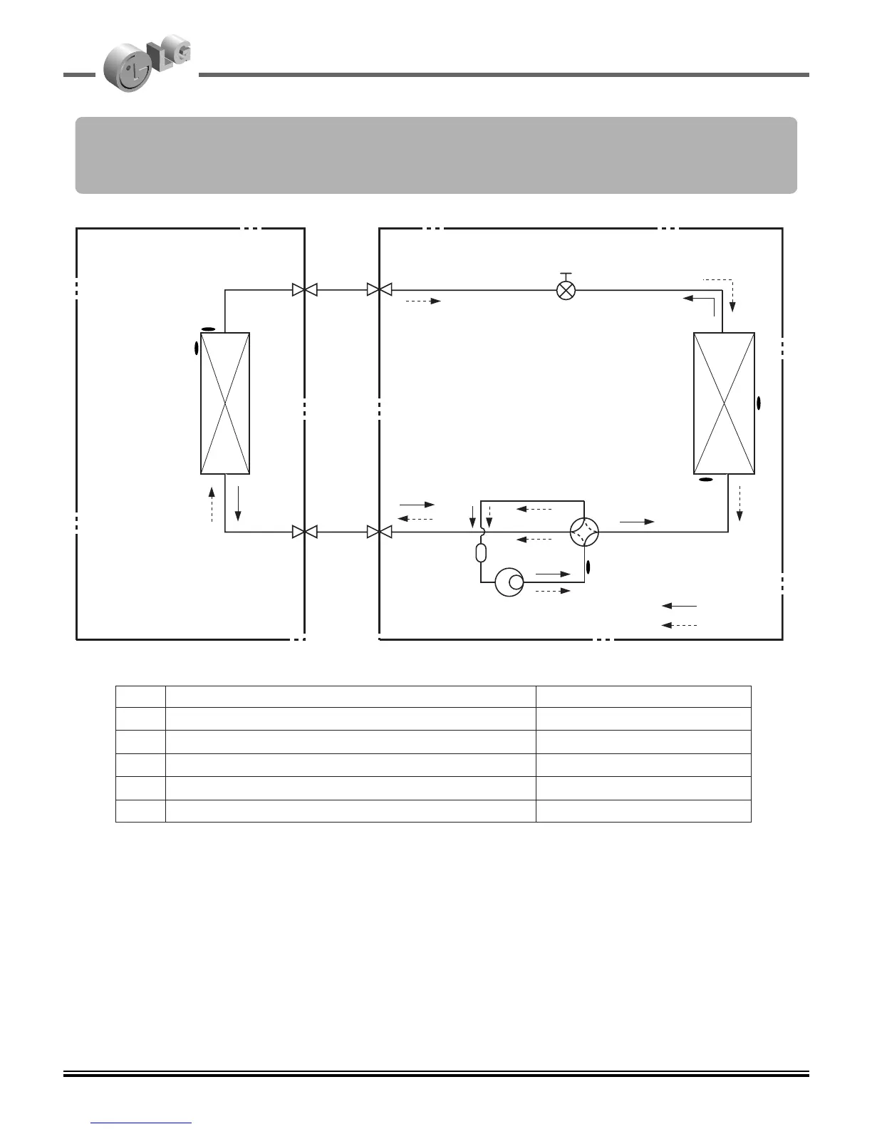
7. Refrigerant cycle diagram
Model no: AS-W096ADR0,AS-W0964GG1, AS-W096E*H2, AS-W096F1G2,
AS-W096F*G2, AS-W096E1G0, AS-W126E1G0, AS-W126ADR0,
AS-W126E*H2, AS-W126F1G2, AS-W126F*G2, AS-W1264GG1
Indoor Unit Outdoor Unit
Heat
Exchanger
(Evaporator)
Heat
Exchanger
(Condenser)
Compressor
Accumulator
Gas Side
3-Way Valve
2-Way Valve
Liquid Side
Cooling
Heating
Th1
Th2
Th4
Th5
Th3
LOC. Description PCB Connector
Th1 Thermistor for indoor air temperature
CN-TH1(INDOOR)
Th2 Thermistor for evaporating temperature
CN-TH1(INDOOR)
Th3 Thermistor for discharge pipe temperature
CN-D_PIPE(OUTDOOR)
Th4 Thermistor for condensing temperature CN-TH1(OUTDOOR)
Th5 Thermistor for outdoor air temperature
CN-TH1(OUTDOOR)
EEV
 Loading...
