Do you have a question about the LG ATNH486DLFC and is the answer not in the manual?
| Type | Split System |
|---|---|
| Refrigerant | R410A |
| Cooling Capacity | 48000 BTU |
| Heating Capacity | 48000 BTU |
| Power Supply | 208/230V, 60Hz |
| Operating Temperature (Cooling) | 5°C to 43°C |
| Operating Temperature (Heating) | -15°C to 24°C |
Details the structure and components of indoor unit model numbers.
Details the structure and components of outdoor unit model numbers.
Safety measures to follow during the installation process.
Safety measures to follow during the operation of the unit.
Lists model names and capacities for various indoor units.
Lists model names and capacities for outdoor units.
Lists accessory model numbers and their intended uses.
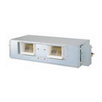
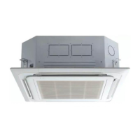
Visual representations of different indoor unit models.
Visual representations of different outdoor unit models.
Physical dimensions for TE chassis cassette indoor units.
Physical dimensions for TF chassis cassette indoor units.
Physical dimensions for TD chassis cassette indoor units.
Physical dimensions for convertible indoor units.
Physical dimensions for concealed duct indoor units.
Physical dimensions for the AUUH488C outdoor unit.
Physical dimensions for the AUUH728C outdoor unit.
Physical dimensions for the AUUH1008C outdoor unit.
Detailed technical specifications for indoor units.
Detailed technical specifications for outdoor units.
Tables detailing MPS Variable system combinations and capacities.
Installation procedure for cassette type indoor units.
Specific steps for ceiling installation, including dimensions.
Steps for performing electrical wiring during installation.
Procedure for installing the decorative panel.
Guidelines and procedures for installing the drain pipe.
List of standard and optional accessories for installation.
Installation procedure for convertible type indoor units.
Steps for connecting cables to the indoor unit.
Requirements and procedures for thermal insulation.
Procedure to verify the functionality of the drainage system.
Steps and techniques for connecting refrigerant pipes.
Instructions for mounting and setting up the remote controller.
Guidelines for installing the AUUH728C outdoor unit.
Methods for installing multiple units in proximity.
Guidelines for installing the AUUH1008C outdoor unit.
Instructions for securely mounting outdoor units.
Safe procedures for lifting and handling outdoor units.
Guidelines for refrigerant pipe length and height differences.
Detailed steps for connecting refrigerant piping.
Procedures for charging the system with refrigerant.
Information on branch pipe types and connection specifications.
Steps for applying thermal insulation to pipes.
General guidelines and precautions for wiring connections.
Steps for automatically assigning addresses to indoor units.
Method for operating multiple indoor units simultaneously.
Procedures for verifying the installation after completion.
Overview of main unit controls, indicators, and display functions.
Operation logic for defrosting during heating mode.
Operation modes utilizing fuzzy logic for temperature and humidity control.
Functions for setting on-timers, off-timers, and sleep timers.
Modes like Chaos Swing, Jet Cool, and Auto Restart.
Modes for forced operation and buzzer feedback.
Detailed explanation of CST type remote controller operations.
Detailed explanation of duct type remote controller operations.
Detailed explanation of convertible type remote controller operations.
System utilizing two thermistors for temperature sensing.
Adjusting indoor fan speed based on ceiling height for cassette units.
Setting external static pressure for duct type units.
Step-by-step guide for setting the external static pressure.
Highlights key features of the control devices.
Description of the simple central control system.
Explanation of individual components and their functions.
Visual guides to system wiring and central control connections.
Methods for setting up PI485 network units and TPS Inverter Multi.
Procedure for setting indoor unit addresses.
Steps for performing a test run of the system.
Sequence of installation steps and wire connection details.
Instructions for setting rotary and DIP switches.
Introduction to the Deluxe Central Control system.
Key features and advantages of the Deluxe Central Control.
Detailed functions including GUI, scheduling, and stability.
Overview of major functions like system control and setup.
System setup diagram and key technical specifications.
Electrical schematics for indoor units, including cassette type.
Electrical schematics for duct type indoor units.
Electrical schematics for convertible type indoor units.
Electrical schematics for outdoor units (AUUH488C/728C/1008C).
Visual representation of system wiring for various unit types.
Wiring diagrams specific to outdoor units.
Visual guide to component placement on various PCBs.
Component layout on outdoor unit PCBs.
Component layout on the solder side of PCBs.
Refrigerant piping diagrams for AUUH488C models (Duo, Trio, Quartet).
Refrigerant piping diagrams for AUUH728C models (Duo, Trio, Quartet).
Refrigerant piping diagrams for AUUH1008C models (Duo, Trio, Quartet).
Guide for diagnosing issues related to the refrigerant cycle.
Troubleshooting steps for electronic parts and PCBs.
Troubleshooting guide for remote control operation issues.
Troubleshooting steps when the cooling function is not working.
Troubleshooting steps when the heating function is not working.
Troubleshooting steps when the indoor fan does not operate.
Troubleshooting steps when the vertical louver fails to operate.
Explanation of the unit's self-diagnosis feature and error codes.
Detailed steps for common error codes (CH01, CH02, CH06).
Steps to diagnose and resolve communication errors.
Steps to diagnose and resolve drain pump or float switch issues.
Steps to diagnose and resolve indoor/outdoor communication errors.
Steps to diagnose DC Peak errors related to compressor.
Steps to diagnose errors related to current sensing.
Steps for diagnosing pressure switch and voltage errors.
Steps for diagnosing compressor position and PSC fault errors.
Steps for diagnosing pipe temperature sensor errors.
Steps for diagnosing various sensor errors (CH41, CH44-47, CH65).
Steps for diagnosing capacity and EEPROM checksum errors.
Steps for diagnosing phase errors.
Steps for diagnosing condenser and heat sink temperature errors.
Description and diagram of 3-way valves (Liquid and Gas sides).
Procedure for pumping down refrigerant before servicing.
Procedure for evacuating the refrigerant system.
Procedure for charging the system with refrigerant.
Operational functions specific to ceiling cassette units.
Operation logic for heating mode, including fan and compressor control.
Control logic to prevent cold starts by managing indoor fan rotation.
Operational functions specific to ceiling duct units.
Operational functions specific to ceiling & floor units.
Control logic to prevent cold starts for specific unit types.
Fundamental operational controls for compressor, fan, and valves.
Temperature ranges defining cooling and heating operation steps.
Control logic for the Electronic Expansion Valve.
Control logic based on compressor discharge temperature.
Control logic for managing outdoor unit fan speed and operation.
Control logic for the reversing valve operation.
Special operational modes, including detailed defrost control.
Logic for equalizing oil levels between compressors.
Protection mechanisms based on discharge pipe temperature.
Control logic based on outdoor pipe temperature.
Function to detect and prevent abnormal sensor readings.
Functionality of high/low pressure switches for protection.
Exploded views for various indoor unit chassis types.
Replacement parts lists for indoor unit chassis.
Exploded views for AUUH488C outdoor unit.
Replacement parts list for AUUH488C outdoor unit.
Exploded view for AUUH728C outdoor unit.
Replacement parts list for AUUH728C outdoor unit.
Exploded view for AUUH1008C outdoor unit.
Replacement parts list for AUUH1008C outdoor unit.
Exploded view for PT-HEC1 indoor unit.
Exploded view for PT-HFC indoor unit.
Exploded view for PT-HDC1 indoor unit.
Replacement parts lists for specific indoor unit models.

![Preview: LG ATNH24GPLED[UT24 NPD]](https://data.easymanua.ls/products/561090/200x200/lg-atnh24gpled-ut24-npd.webp)