Do you have a question about the LG Flatron E2260S and is the answer not in the manual?
Critical warnings for safe servicing before starting.
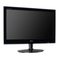
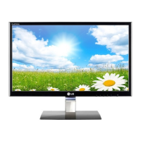
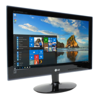
Display size, resolution, pixel pitch, and surface treatment.
Input voltage, current, and power consumption details.
Horizontal and vertical frequency ranges for video signals.
Temperature and humidity limits for operation and storage.
Monitor dimensions and weight with and without stand.
Identifying parts crucial for safety that require specific replacement.
Safe practices for mounting and handling the LCD module.
Warnings about high voltage in inverter circuits and handling precautions.
Cautions regarding battery types and proper disposal methods.
Procedures for unplugging, testing, cleaning, and grounding.
Methods to protect sensitive electronic components from static electricity.
Guidelines for proper soldering iron use and solder removal.
Specific procedures for replacing ICs, transistors, diodes, fuses, and resistors.
Procedures for using jumper wires to mend broken circuit board traces.
Explanation of signal processing, pixel clock generation, and resolution scaling.
Description of voltage regulators and power conversion circuits.
Function of the microcontroller in sync detection and system control.
Configuring BIOS for the parallel port mode required by the EDID tool.
Step-by-step process for loading, verifying, and writing monitor EDID information.
Details on available service functions like aging, panel type, and color adjustments.
Flowchart for troubleshooting power-related problems.
Troubleshooting steps for LIPS backlight issues causing no display.
Troubleshooting steps for MSTAR scaler issues causing no display.
Steps to check H/V sync signals for DPM related faults.
Guide to check AC line, adapter, and main board for power faults.
Troubleshooting steps for raster issues when the backlight lamp is off.
Schematic for the primary logic and control board.
Schematic of the monitor's output ports and panel connection interface.
Schematic for the power input, regulation, and backlight driver circuits.
Schematic detailing the video scaler IC and its associated components.
Schematic for the DC-DC converter and LED driver IC.
Schematic for the monitor's physical button control panel.
Schematic for the status indicator LED board.
| Screen Size | 21.5 inches |
|---|---|
| Resolution | 1920 x 1080 |
| Panel Type | TN |
| Brightness | 250 cd/m² |
| Contrast Ratio | 1000:1 |
| Response Time | 5 ms |
| Viewing Angle | 170°/160° |
| Connectivity | VGA, DVI-D |
| Aspect Ratio | 16:9 |
| Contrast Ratio (Dynamic) | 5, 000, 000:1 |
| Weight | 3.3 kg |