Do you have a question about the LG FLATRON E2350V and is the answer not in the manual?
Details of the LCD panel, including type, size, and pixel pitch.
Specifies viewing angles, luminance, and contrast ratios.
Describes signal types, input signals, and operating frequencies.
Lists the maximum supported resolutions for Analog, Digital, and HDMI.
Details power supply specifications including adaptor input and power consumption.
Outlines operating temperature, humidity, and MTBF for the unit.
Provides the physical dimensions of the monitor with tilt and swivel.
States the net and gross weight of the monitor with tilt and swivel.
Details the pin assignments for the DVI-D digital connector.
Highlights critical safety components and the need for specified replacement parts.
Provides guidelines for safely handling the LCD module and backlight unit.
Warns about electric shock hazards, especially with the inverter circuit.
General guidelines for safe servicing, including power disconnection and testing.
Explains how to handle ES devices to prevent damage from static electricity.
Covers best practices for soldering, including iron temperature and solder type.
Details the procedure for removing and replacing Integrated Circuits.
Explains how to remove and replace small-signal and power transistors.
Outlines the process for removing and replacing diodes.
Describes how to replace fuses and conventional resistors.
Provides guidelines for repairing damaged copper foil on circuit boards.
Specific steps for repairing copper patterns at IC connections using jumper wires.
Technique for repairing copper patterns at non-IC connections with jumper wires.
Explains the function of the video controller, scaler, ADC, and TMDS receiver.
Describes the power supply components, including DC-DC converters and regulators.
Details the MICOM part, including EEPROM, Reset IC, and flash memory.
Instructions for setting up the user port for software interaction.
Steps to read and write EDID data using WinEDID software.
Flowchart to diagnose and resolve no-power issues, including voltage checks.
Troubleshooting steps for when the raster or OSD is not displayed on the LIPS board.
Troubleshooting steps for no raster/OSD on the main board.
Diagnosing and resolving issues related to the DPM (Display Power Management) function.
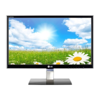
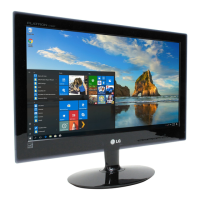
This document is a service manual for the LG FLATRON E2350V (E2350V-PFV.A***AVN) color monitor, identified by chassis number LM99D. It provides comprehensive information for servicing and maintenance, intended for internal use by LG Electronics.
The monitor is a TFT Color LCD Module with a 23.0-inch diagonal active display area and a pixel pitch of 0.266(H) x 0.266(V)mm. Its physical dimensions are 533.2(H) x 312.0(V) x 16.5(D)mm. It supports a color depth of 16.7 million colors and features an AG (Haze 25%), Hard Coating (3H) surface treatment. The operating mode is "Normally White," and it uses a W-LED backlight unit.
Key optical characteristics include a wide viewing angle with a contrast ratio of ≥5, specifically: Left: +75° min., +88°(Typ); Right: -75° min., -88°(Typ); Top: +70° min., +85°(Typ); Bottom: -70° min., -85°(Typ). Luminance ranges from 150(Typ) (Typ.+30)-sRGB to 180(min), 200(Typ)-6500K, and 150(min)-9300K. The contrast ratio is 700(min), 1000(Typ), with a DFC (Digital Fine Contrast) ratio of 5,000,000:1 (Typ).
The monitor supports various signal inputs, including Analog (R, G, B) with a voltage level of 0~0.7 V and an input impedance of 75 Ω, and Digital (Separate Sync). Operating frequencies for Analog/Digital are: Horizontal: 30~83kHz, Vertical: 56~75Hz. For HDMI, the frequencies are: Horizontal: 30~83kHz, Vertical: 56~61Hz.
Maximum resolutions supported are 1920 x 1080@60Hz for Analog, Digital, and HDMI inputs.
The power supply is a built-in adaptor with an input of AC 100-240V~, 50/60Hz, 1.0A. Power consumption in normal operation is less than 30 W (max) or 28 W (typ), with a purple LED color. In standby, suspend, and DPMS off modes, consumption is less than 1 W, with a purple blinking LED. When the power switch is off, consumption is less than 0.5 W, and the LED is off.
Environmental specifications include an operating temperature of 10°C~35°C (50°F~95°F) and relative humidity of 10%~80% (non-condensing). The Mean Time Between Failures (MTBF) is 50,000 hours with a 90% confidence level, and the lamp life is 30,000 hours (Min).
The monitor's dimensions (with tilt/swivel) are: Width: 55.85cm (21.98 inches), Depth: 19.80 cm (7.80 inches), Height: 41.75 cm (16.43 inches). Its weight (with tilt/swivel) is: Net Weight: 3.3kg (7.28 lbs), Gross Weight: 5.43 kg (11.97 lbs).
The manual includes detailed sections on precautions, timing charts, disassembly procedures, block diagrams, and descriptions of the block diagram components.
The "Description of Block Diagram" outlines three main parts:
The LIPS (LG Inverter Power Supply) Board Block Diagram details the power supply operation:
The manual also covers adjustment procedures, including EDID (Extended Display Identification Data) read and write using WinEDID.exe, allowing modification of manufacturing week, year, and serial number.
A "SERVICE OSD" (On-Screen Display) menu is accessible by turning off the power, waiting 5 seconds, then pressing MENU and POWER simultaneously for 1 second. This menu offers advanced settings:
Troubleshooting guides are provided for common issues:
The manual also contains an exploded view diagram for component identification and a wiring diagram illustrating the connections within the monitor.
Safety precautions are emphasized throughout the manual, particularly regarding handling electrostatically sensitive (ES) devices, high voltage circuits, and specific components marked for safety. It advises against modifying original designs and stresses the use of manufacturer-specified replacement parts to prevent hazards. Proper soldering and circuit board repair techniques are also detailed.