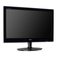
Do you have a question about the LG FLATRON E2040S and is the answer not in the manual?
Details on the TFT Color LCD module specifications.
Specifies viewing angles, luminance, and contrast ratio.
Covers sync signal type, video input, and operating frequency.
Defines the maximum display resolution supported.
Outlines power requirements and consumption modes.
Specifies operating and storage temperature/humidity ranges.
Provides physical dimensions and product weight.
Identifies critical safety components for replacement to prevent hazards.
Guidelines for safely handling the LCD module and its backlight unit.
Emphasizes caution regarding high voltage and inverter circuit handling.
Warning about explosion risk if batteries are replaced with incorrect types.
Caution to use plastic screwdrivers to prevent shock during service.
Essential rules for all servicing operations, prioritizing safety.
Techniques to prevent damage to ESD-sensitive components like ICs and transistors.
Best practices for soldering, including iron temperature, tip care, and solder type.
Procedures for replacing ICs, transistors, diodes, fuses, and resistors.
Guidelines for repairing damaged copper patterns on printed circuit boards.
Techniques for installing jumper wires on circuit board connections.
Table detailing timing parameters (dot clock, frequency, display, porches) for various modes.
Steps to remove the monitor base using the release button.
Instructions for opening latches and removing the back cover of the monitor.
Procedures for pulling out the keyboard and disconnecting FFC/converter cables.
Steps to unscrew and remove main/converter boards and the front bezel.
Steps to disassemble the rear cover and the main hinge assembly.
Instructions for detaching the hinge top, hinge, and stand components.
Diagram of the main scalar IC (NT68168FG/B) with crystal, flash, and input ports.
Shows LDO for 3.3V, power input, and panel power sequence control.
Diagram illustrating the converter circuit, including boost, OVP, and feedback paths.
Shows the current balance control IC (ta9690) and its ON/OFF and DIM inputs.
Explains the role of the scalar, ADC, TMDS, and LVDS transmitter in video processing.
Details power supply to boards and the Micom's function in sync and data control.
Explains the functions of boost, on/off, and dim circuits for LED control.
Describes the IC's control over LED current, OVP, and feedback detection.
Instructions for BIOS configuration to set parallel port mode to SPP.
Steps for connecting the monitor, loading files, and writing EDID data.
Guide to inputting manufacturer, product code, and model name in the EDID tool.
How to check the PASS/FAIL status and ensure data integrity.
Procedure to turn off power and press specific buttons to enter service mode.
Details various options available in the Service OSD menu, like AGING and R/G/B settings.
Flowchart for diagnosing issues when the power indicator is off.
Steps involving voltage measurements at U701 and checking X401 oscillation.
Troubleshooting steps for no OSD display with LIPS backlight.
Checking CN702 and U701 voltages, and BL ON/OFF pulse.
Diagnosing no raster by checking scaler oscillation and sync signals from D-SUB.
Verifying capacitors, crystal, scaler IC, and cable connections for faults.
Steps to diagnose problems related to the Digital Panel Module (DPM).
Checking Horizontal/Vertical sync lines and potential cable or LCD module faults.
Verifying AC line voltage, socket, and adapter functionality.
Checking internal voltages, main board, and considering panel replacement.
Troubleshooting steps when the lamp is off and no image is displayed.
Verifying CN702 voltage, ON/OFF signal, DIM, PANEL_VCC, and related components.
Diagram illustrating the electrical connections between major components.
Illustration identifying parts with special safety-related characteristics.
Exploded view showing the physical arrangement and assembly of monitor parts.
Schematic showing D-SUB connector signals connected to the main scaler IC.
Details the DDC interface and VGA signal paths within the scaler circuitry.
Schematic illustrating the Low-Voltage Differential Signaling (LVDS) connections to the LCD panel.
Shows the power supply (PANEL_VCC) and control signals routed to the panel.
Diagrams for the MP1584EN DC-DC converter and AME8815/AP1117 voltage regulators.
Schematic showing connections to the main scalar controller IC and its peripherals.
Details connections for serial flash memory (PM25LV020) and keyboard input.
Schematic of the TA9690GN LED driver IC, including its control and feedback circuits.
Diagrams illustrating the boost converter, OVP, and current sense circuits for LED backlight.
Provides detailed pinouts for various connectors (CN801-CN809) related to the converter section.
| Screen Size | 20 inches |
|---|---|
| Panel Type | TN |
| Resolution | 1600 x 900 |
| Brightness | 250 cd/m² |
| Contrast Ratio | 1000:1 |
| Response Time | 5 ms |
| Viewing Angle | 170° (H) / 160° (V) |
| Aspect Ratio | 16:9 |
| Input | Analog |
| Weight | 3.2 kg |
| Contrast Ratio (Dynamic) | 5000000:1 |
| Connectivity | VGA |
| Input Connectors | D-Sub |