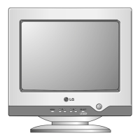
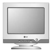
1. PICTURE TUBE
Size : 19 inch (Flat Slot Mask)
DefIection Angle : 90°
Neck Diameter : 29.1 mm
Phosphor : P22
Slot Pitch : 0.25 mm
Face Treatment : W-ARAS, Internal Anti-Glare
Function : TCO 03, TCO99
2. SIGNAL
2-1. Horizontal & Vertical Sync
1) Input Voltage Level: Low= ≤0.8V, High= ≥2.1V
2) Sync Polarity : Positive or Negative
2-2. Video Input Signal
1) Voltage Level : 0~0.7 Vp-p
a) Color 0, 0 : 0 Vp-p
b) Color 7, 0 : 0.467 Vp-p
c) Color 15, 0 : 0.7 Vp-p
2) Input Impedance : 75 Ω
3) Video Color : R, G, B Analog
4) Signal Format : Refer to the Timing Chart
2-3. Signal Connector
15 Pin D-Sub Connector
2-4. Scanning Frequency
Horizontal : 30~98 kHz
Vertical : 50~160 Hz
3. POWER SUPPLY
AC 100~240V, 50/60HZ, 2.5A Max
AC 200~240V, 50Hz, 1.5A Max.(PFC version)
3-2. Power Consumption
3-3. PFC: More than 0.72 at 230VAC
4. DISPLAY AREA
4-1. Active Video Area :
• Max Image Size - 365.8 x 274.3mm (12.91" x 9.61")
• Preset Image Size - 350 x 262 mm (12.20" x 9.06")
4-2. Display Color : Full Colors
4-3. Display Resolution : 1600 Dots x 1200Lines
4-4. Video Bandwidth : 203MHz
5. ENVIRONMENT
5-1. Operating Temperature: 0°C~40°C (32°F~103°)
5-2. Operating Humidity : 10%~80%
5-3. Altitude(Operating) : 5,000m(Reliability)
6. DIMENSIONS (with TILT/SWIVEL)
Width : 443 mm (17.44")
Depth : 458 mm (18.03")
Height : 450 mm (17.72")
7. WEIGHT (with TILT/SWIVEL)
Net Weight : 20.9 kg (46.08 lbs)
Gross Weight : 24.4 kg (53.79 lbs)
CONTENTS
SPECIFICATIONS
- 2 -
SPECIFICATIONS ................................................... 2
SAFETY PRECAUTIONS ........................................ 3
TIMING CHART ....................................................... 4
OPERATING INSTRUCTIONS ................................ 5
WIRING DIAGRAM ................................................. 6
DISASSEMBLY ....................................................... 7
BLOCK DIAGRAM ................................................... 8
DESCRIPTION OF BLOCK DIAGRAM.....................9
ADJUSTMENT ....................................................... 11
TROUBLESHOOTING GUIDE .............................. 13
EXPLODED VIEW.................................................. 20
REPLACEMENT PARTS LIST .............................. 22
PIN CONFIGURATION .......................................... 28
SCHEMATIC DIAGRAM......................................... 31
PRINTED CIRCUIT BOARD................................... 33
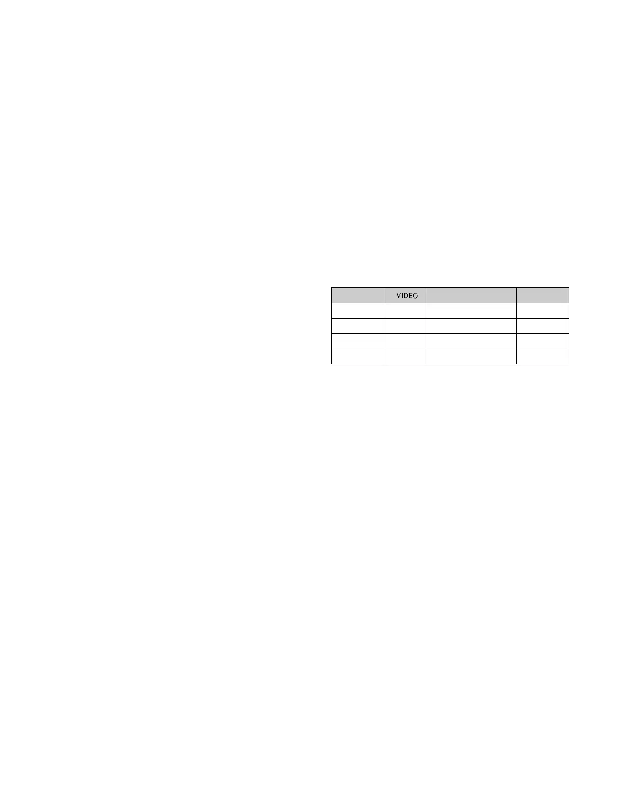
POWER CONSUMPTION
less than 120W
less than 8W
less than 8W
less than 3W
LED COLOR
GREEN
AMBER
AMBER
AMBER
MODE
MAX
STAND-BY
SUSPEND
DPMS OFF
Yes
No
No
No
 Loading...