Do you have a question about the LG GR-M562Y*X/M602Y*X and is the answer not in the manual?
Procedure for testing and refilling the refrigeration system with R-134a.
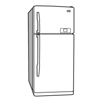
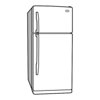
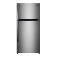
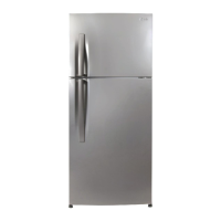
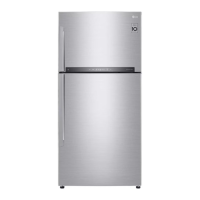
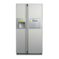
Illustrates and labels various components of the refrigerator.
Instructions for removing the freezer and refrigerator doors.
Steps to remove and disconnect the door switch.
Procedure for removing the fan and motor assembly.
Steps to remove and replace the defrost control assembly.
Instructions for replacing freezer and refrigerator lamps.
Procedure for removing the control box.
Explains the compressor's function, composition, and usage notes.
Details the PTC-starter's composition, role, and usage precautions.
Defines the OLP, its function, and usage notes.
Troubleshooting flowcharts for compressor and related electrical parts.
Troubleshooting flowcharts for PTC and OLP components.
Troubleshooting flowcharts for various other electric components.
A chart correlating complaints with points to check and remedies.
Table detailing causes, states, and remarks for refrigerating cycle issues.
Flowchart for detecting refrigerant leakage.
Details specifications for welding rod, flux, drier, vacuum, and gas.
Describes basic operation and temp control modes for different models.
Explains the Super Cool feature, its activation, and duration.
Details the fan speed control logic in the freezer.
Describes the alarm function triggered by doors left open.
Describes the buzzer sound triggered by button presses.
Explains when and how the defrosting cycle is performed.
Outlines the sequence of component activation during power-on or test mode.
Details the noise attenuation and SMPS parts of the power circuit.
Explains the circuit generating the base clock for the MICOM.
Describes the circuit for initializing MICOM functions upon power-up.
Details the circuits for driving loads, buzzers, and detecting open doors.
Explains buzzer drive conditions and alarm signals.
Details the circuit check for open door detection.
Describes the circuit for detecting ambient, freezer, and refrigerator temperatures.
Input circuit for detecting test switch signals.
Circuits for less cooling and overcooling compensation.
Circuit for detecting key presses and turning on display LEDs.
Troubleshooting chart for power source and cooling issues.
Troubleshooting chart for refrigerator temperature and defrosting issues.
Diagram showing the layout of components on the main PCB.
Detailed list of replaceable parts for the main PCB.
Details of the display PCB assembly and its components.
Lists the components for the display PCB with I-MICOM.
Lists components related to the V-LED display.
Diagram showing the exploded view of the refrigerator.
| Energy Efficiency Class | A++ |
|---|---|
| Refrigerant | R600a |
| Smart Diagnosis | Yes |
| Door Cooling | Yes |
| Multi Air Flow | Yes |
| Water Dispenser | Yes |
| Defrost System | Frost Free |
| Display | LED |
| Dimensions (W x H x D) | 730 mm |
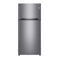
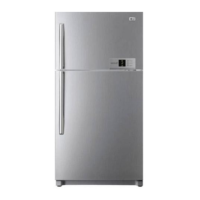
| Color | Stainless Steel |