3. TECHNICAL BRIEF
- 55 -
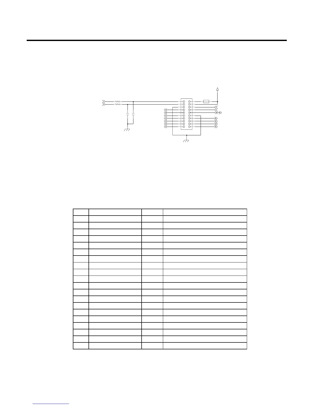
3.10.5.2 VGA Camera Interface
The VGA Camera module is connected to main board with 20pin Board to Board connector
(AXK720145). Actually, there is a linking FPCB to connect camera module to the main board.
Its interface is dedicated camera interface port in MSM6275. The camera port supply 24MHz master
clock to camera module and receive 12MHz pixel clock (30fps), vertical sync signal, horizontal sync
signal, reset signal and 8bits data from camera module. The camera module is controlled by I2C port
from MSM6275.
Table. Interface between Camera Module and Main Board (in camera module)
Actually, between VGA camera FPCB connector and Main Board connector.
DataOCAM_DATA(1)6
DataOCAM_DATA(0)5
Clock for Camera Data OutOCAM_PCLK4
GNDGNDGND3
System Clock (Master Clock) 24MICAM_SYSCLK2
DataOCAM_DATA(6)11
DataOCAM_DATA(5)10
DataOCAM_DATA(4)9
DataOCAM_DATA(3)8
DataOCAM_DATA(2)7
I2C Data (Command)I/OI2C_SDA16
GNDGNDGND15
SPEAKER-OCAM_HSYNC14
GNDOCAM_VSYNC13
DataOCAM_DATA(7)12
Camera Analog, I/O PowerIVCAM_2.8V20
Camera Analog, I/O PowerIVCAM_2.8V19
Camera Reset SignalIV_CAM_RESET_N18
I2C ClockII2C_SCL17
VGA Camera PWR Down EnableIVC_IO_OFF1
NotePortNameNo
 Loading...