Introduction 9
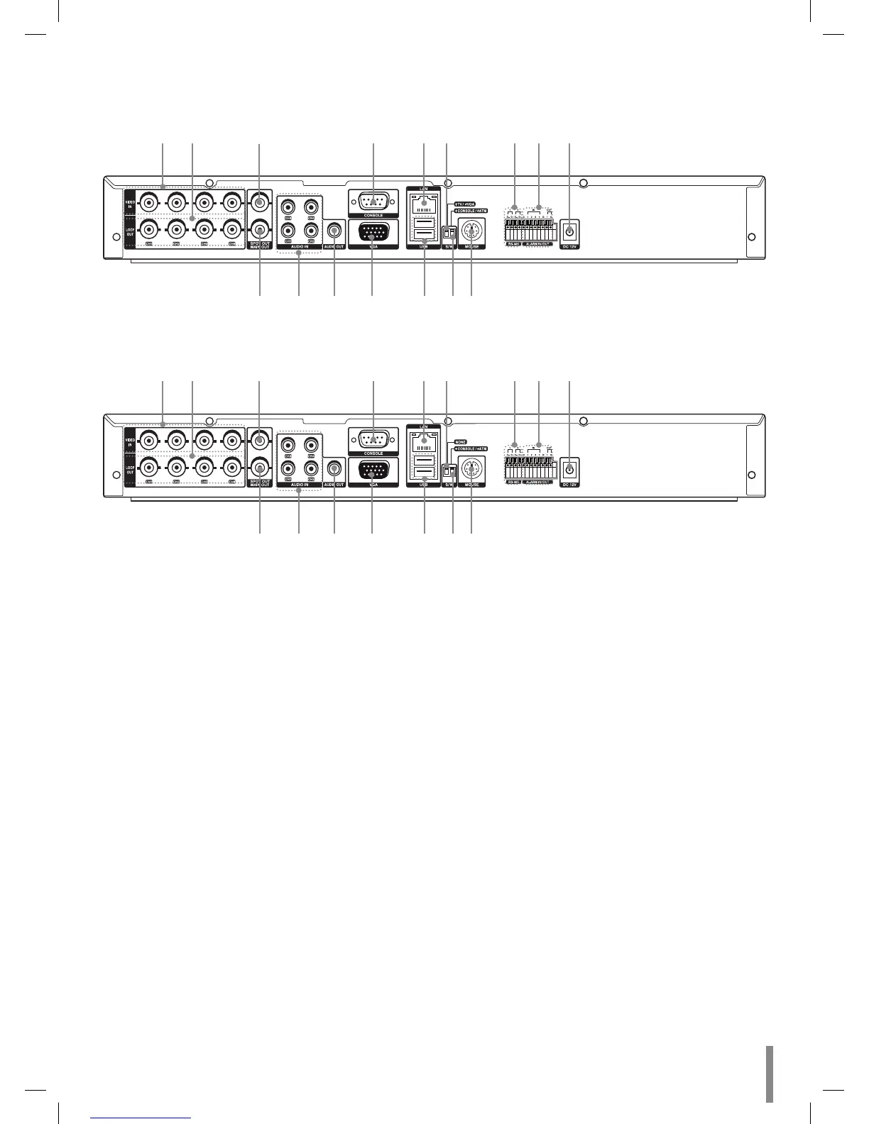
Rear Panel
Rear panel with the TV or VGA output select switch.
ab c d ef ghi
jklm nop
Rear panel without the TV or VGA output select switch.
ab c d ef ghi
jklm nop
a VIDEO INPUT
Connect the camera’s video output to these BNC con-
nectors.
b LOOP OUT
The signal from VIDEO INPUT connector is looped out
to this connector.
c SPOT-OUT (BNC Type Connector)
Connect to spot monitor or display device.
d CONSOLE (RS-232C Connector)
Used to connect to a host device equipped with RS-
232C connector (such as a personal computer). This
unit can be controlled from other devices via this con-
nector.
e LAN Port
Connect the ethernet 10/100Mbps network cable for
controlling this unit via a PC network.
f TV or VGA output select switch. (This swith is optional
by models.)
g RS-485 Terminals
Connect RS-485 compatible cameras.
Connect the LKD1000 controller to D2 terminal.
h ALARM IN/OUT Terminals
IN: Input terminals for alarm(relay) signal.
OUT: Output terminals for alarm(relay) signal.
i Power Cord Inlet (DC 12V)
Connect the power plug.
j MAIN-OUT (BNC Type Connector)
Connect to main monitor or display device.
k AUDIO INPUT
Connect the audio output of an external device.
l AUDIO OUT
Connect the audio input signal of an external device.
m VGA
Connect a VGA monitor.
n USB Ports
Connect an optional extension USB device.
o CONSOLE or ATM output select switch.
(ATM is a reserved function.)
p MOUSE
Connect an mouse device (PS2 Type).
-
-