Do you have a question about the LG LHD625 and is the answer not in the manual?
Guidelines for servicing the unit, covering pick-up handling and general repair notes.
Instructions for handling Electro statically Sensitive Devices (ESD) and identifying safety symbols.
Procedures to access system information and settings via hidden remote commands.
Step-by-step instructions for updating the unit's firmware using a USB device.
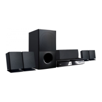
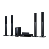
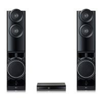
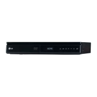
Detailed technical specifications including general, inputs/outputs, amplifier, and tuner.
Troubleshooting guide for common digital display and media playback issues.
Targeted repair solutions for frequent problems, including component identification.
Systematic troubleshooting flowcharts for power supply and system part issues.
Technical details, test points, and waveforms for system analysis and debugging.
Illustrates physical connections and cable routing between major unit modules.
Comprehensive circuit schematics for SMPS, Main, AMP, and I/O sections.
Lists critical ICs, connectors, and their expected voltage levels during operation.
Top and bottom views of printed circuit boards showing component layouts.
Visual breakdowns of the unit's cabinet, main frame, deck mechanism, and speakers.
| Power Output | 1000W |
|---|---|
| Number of Channels | 5.1 |
| Blu-ray Playback | Yes |
| DVD Playback | Yes |
| USB Playback | Yes |
| HDMI Inputs | 1 |
| Playable Disc Types | BD, DVD, CD |
| Radio | FM |
| Remote Control | Yes |
| Audio Formats Supported | Dolby Digital, DTS |
| Playable File Formats | MP3, WMA, JPEG |
| Connectivity | Bluetooth |