Owner’s Manual 29
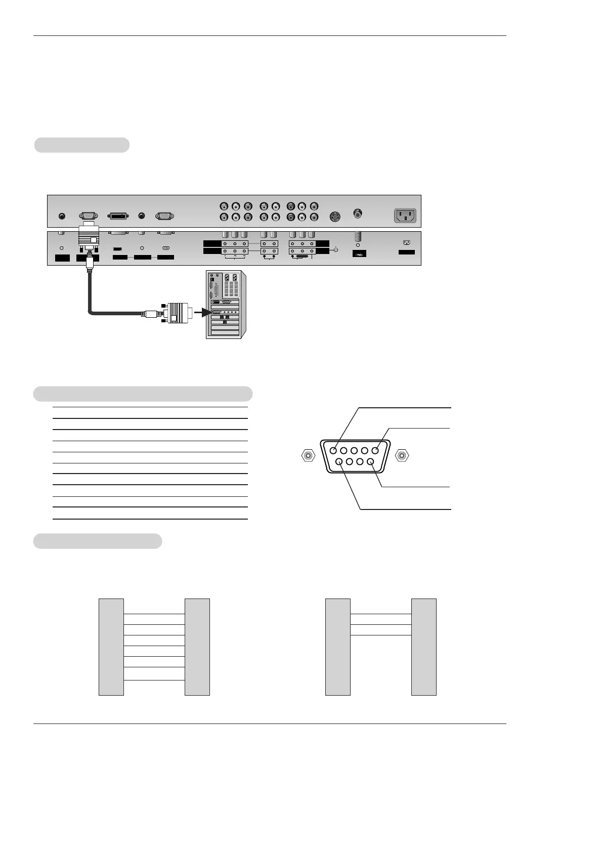
External Control Device Setup
No. Pin name
1 No connection
2 RXD (Receive data)
3 TXD (Transmit data)
4 DTR (DTE side ready)
5 GND
6 DSR (DCE side ready)
7 RTS (Ready to send)
8 CTS (Clear to send)
9 No Connection
1
5
6
9
2
3
5
4
6
7
8
RXD
TXD
GND
DTR
DSR
RTS
CTS
TXD
RXD
GND
DSR
DTR
CTS
RTS
PC
7-Wire Configurations
(Standard RS-232C cable)
D-Sub 9
3
2
5
6
4
8
7
PDP
D-Sub 9
2
3
5
4
6
7
8
RXD
TXD
GND
DTR
DSR
RTS
CTS
TXD
RXD
GND
DTR
DSR
RTS
CTS
PC
3-Wire Configurations
(Not standard)
D-Sub 9
3
2
5
4
6
7
8
PDP
D-Sub 9
- Connect the RS-232C input jack to an external control device (such as a computer or an A/V control system)
and control the Monitor’s functions externally.
- Connect the serial port of the control device to the RS-232C jack on the Monitor back panel.
- RS-232C connection cables are not supplied with the Monitor.
T
T
ype of Connector; D-Sub 9-Pin Male
ype of Connector; D-Sub 9-Pin Male
RS-232C Configurations
RS-232C Configurations
External Control Device Setup
External Control Device Setup
RS-232C Setup
RS-232C Setup
 Loading...