10
MULTI V Space II Installation Manual
Due to our policy of continuous product innovation, some specifications may change without notification.
©LG Electronics U.S.A., Inc., Englewood Cliffs, NJ. All rights reserved. “LG” is a registered trademark of LG Corp.
• Multi V Space II should be installed in a soundproofed mechanical
room.
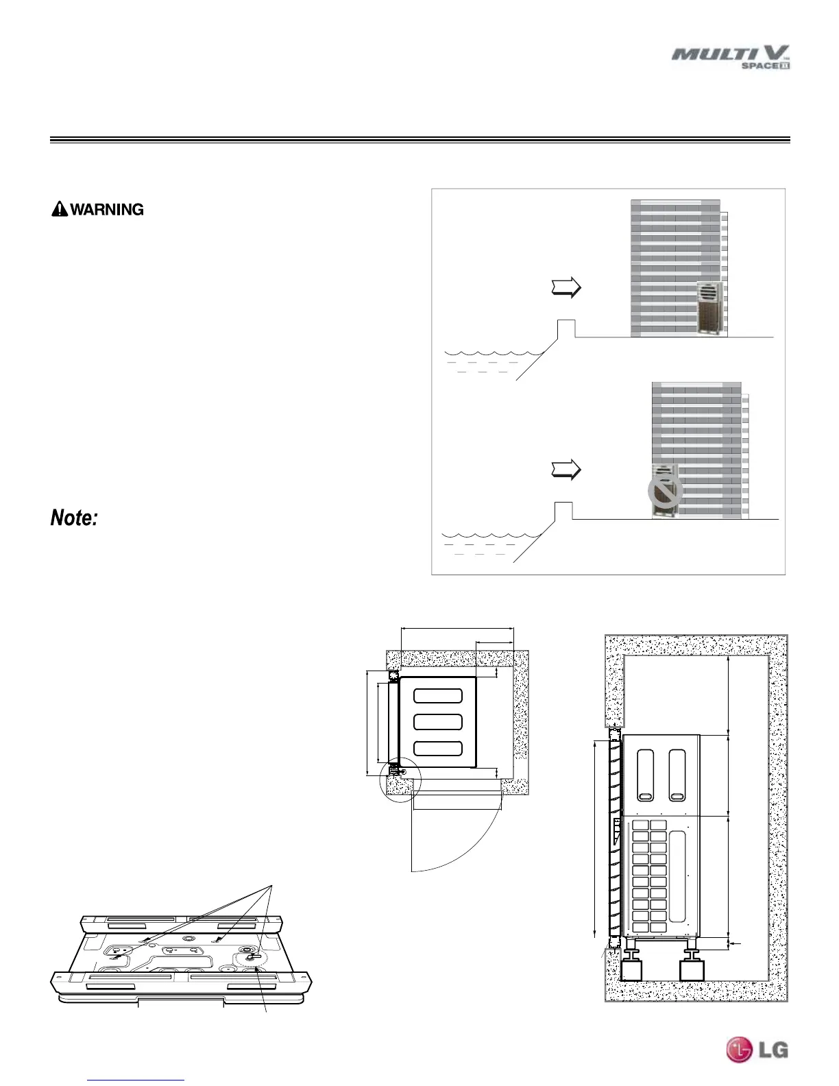
• Avoid installing the Space II unit where it would be directly exposed
to ocean winds.
• Install the outdoor unit on the side of the building opposite from
direct ocean winds.
• Select a location with good drainage.
• Periodically clean dust or salt particles off of the heat exchanger
with water.
• If the Space II unit must be placed in a location where it would be
subjected to direct ocean winds, install a concrete windbreaker
strong enough to block any winds.
Additional anti-corrosion treatment may need to be applied to the
outdoor unit at oceanside locations.
Ocean winds may cause corrosion, particularly on the condenser
and evaporator ns, which, in turn could cause product malfunction
or inefcient performance.
Ocean winds
Ocean winds
GENERAL INSTALLATION GUIDELINES
Oceanside Applications / Required Clearances
Figure 1: Oceanside Placement.
Oceanside Applications
Required Clearances
• Allow adequate clearance for the system louvers
(see figure at right).
• Automatic louver installation = 6 inches
• Manual louver installation = 6 inches
• Fixed louver installation = 4 inches (Basic space)
• Place the product so that the door of the Space II
unit's enclosure can be opened completely for
easier installation and service access.
Water Drain Outlet
• An outlet is required to allow water drainage from
the bottom of the Space II unit enclosure (conden-
sation could form during unit operation).
Figure 2: Required Clearances for Multi V Space II.
20
45
1/2
Min (34 4/5 + 1/5)
25
3/4
Door Width
35
1/2
4 (Min)
4 (Min)
Unit = Inches
(Min) 63 1/5 + 1/5
3 1/2
40 1/2
26 5/8
2 3 5/8
*
*
*
Automatic/Manual Louver = 6” Min.
Fixed Louver = 4” Min.
Figure 3: Water Drain Outlet.