31
Refrigerant Piping Connections
Due to our policy of continuous product innovation, some specifications may change without notification.
©LG Electronics U.S.A., Inc., Englewood Cliffs, NJ. All rights reserved. “LG” is a registered trademark of LG Corp.
The proper design and installation of the refrigerant piping system
is a critical element of the Multi V Space II system. Multi V Space II
requires two pipes between system components – a liquid line and
a vapor line. A properly designed refrigerant piping system ensures
that refrigerant is delivered to the evaporator coils electronic expan-
sion valve (EEV) in a pure liquid state free of gas bubbles. A proper
design also ensures a sufficient refrigerant gas flow rate in the vapor
line that eliminates the possibility of refrigeration oil from collecting in
the vapor lines.
Refrigerant Piping Quality Assurance
LG’s LATS Multi V software makes designing the refrigerant system
easy. LATS Multi V is a Windows
®
-based application that assists the
engineer in the design of the refrigeration distribution pipe system,
verifies the design complies with pipe design limitations, applies
capacity correction factors, and calculates the system refrigerant
charge. The piping system can be entered manually into LATS from
a one-line pipe diagram.
To ensure that the refrigerant piping design meets LG’s quality
standards, a LATS refrigerant piping design must be provided
with every Multi V Space II order. Following the installation, if
any changes or variations to the design are necessary, a new
LATS file must be created and provided to LG prior to system
commissioning to ensure the proper pipe size has not changed.
Adjusting LATS Multi V Output for
Altitude
When a system is installed at elevations significantly above sea
level, the designer must also consider the impact air density has on
the capacity of the indoor and Space II units. LATS does not de-rate
indoor unit capacity for high altitude applications. Locally accepted
altitude correction factors must be applied to indoor unit capacities.
Design Choices
LATS Multi V software is flexible, offering the HVAC system engineer
a choice of two design methods: CAD mode and Tree mode.
CAD Mode
Using the CAD mode, the refrigerant pipe design and layout work is
performed concurrently. Simply import a copy of a plan view drawing
(.dwg format) for floor of the structure into LATS Multi V software.
Multi V air-source units, heat recovery units, and indoor units can be
selected from drag and drop lists and placed on the floor plan draw-
ing(s), and interconnecting pipes between system components will
be drafted directly on the drawing set. LATS will size the refrigerant
piping, certify the design, and provide a detailed materials report and
system schematic. Use the export feature to create a CAD file (.dxf
format) that can subsequently be imported into the building design
drawings.
• Import the building’s architectural CAD (.dwg and .dxf format).
• Import building loads from an external file (.xls and .xlsx format).
• Layout refrigerant piping directly onto an overlay of the building drawing.
• Automatically calculates pipe segment lengths based on drawing layout.
• Creates an export image file for import to the building drawing set
(.dxf format).
• Generates a system engineering report (.xls or .xlsx format).
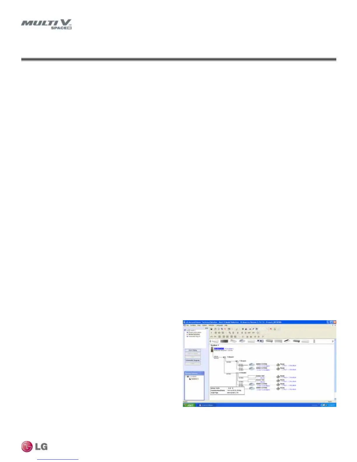
Tree Mode
Using the TREE mode, the engineer can quickly create a one-
line schematic drawing of the Multi V system. Integration of the
engineered pipe system into the building drawings is done at a later
date by the draftsperson using standard drafting software tools.
• Import building loads from an external file (.xls format).
• System components selected using an easy drag and drop
process.
• Automatically analyzes and checks the design complies with most
piping design limitations.
• Sizes refrigerant piping.
• Generates a system engineering report (.xls format).
In either case, LATS Multi V software generates a report file (.xls
format) containing project design parameters, cooling and heating
design day system component performance, and capacity data. The
report calculates the system combination ratio, calculates the system
refrigerant charge, and provides detailed bill of material information
including a list of Multi V outdoor units, air handlers, control
devices, accessories, refrigerant pipe sizes segregated by building,
by system, by pipe size, and by pipe segments.
Figure 30: Screenshot of LATS Pipe System Design Tool in Tree Mode.
Required LATS Multi V Piping Design Software File
REFRIGERANT PIPING CONNECTIONS