28
MULTI V Space II Installation Manual
Due to our policy of continuous product innovation, some specifications may change without notification.
©LG Electronics U.S.A., Inc., Englewood Cliffs, NJ. All rights reserved. “LG” is a registered trademark of LG Corp.
ℓ ≤ 131 feet
Elevation1 ≤98.4 feet
Elevation2 ≤ 49 feet
Length ≤ 230 feet
Space Unit
IDU
IDU
IDU
IDU
IDU
D
Y-branch
To Space
Unit
To Indoor
Units
ℓ
≤
131 feet
Elevation2 ≤ 49
Length ≤ 230 feet
Elevation1 ≤ 98.4 feet
Space Unit
Header
Brazed Cap
IDU
IDU
IDU IDU
IDU
IDU
D
The following is an example of manual pipe size calculations. Designers are highly encouraged to use LATS instead of manual calculations.
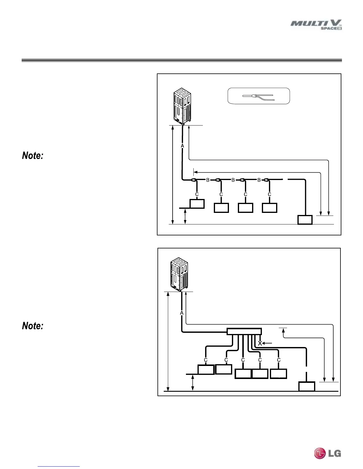
System Using Y-branches
Example: Five (5) indoor units connected
Space II Unit.
IDU: Indoor Units.
A: Main Pipe from Space II Unit to Y-branch.
B: Y-branch to Y-branch.
C: Y-branch to Indoor Unit.
D: Y-branch to Farthest Indoor Unit.
• Always reference the LATS Multi V software
report.
• See pages 29-30 for refrigerant pipe diame-
ter and pipe length tables.
Example: Six (6) indoor units connected
Space II Unit.
IDU: Indoor Units.
Header.
A: Main Pipe from Space II Unit to Header.
C: Header to Indoor Unit.
D: To Farthest Indoor Unit.
System Using a Header
• Indoor units should be installed at a lower
position than the Header.
• Y-branch pipes cannot be used after
Headers.
• Install the Header so that the pipe dis-
tances between the between the con-
nected indoor units are minimized. Large
differences in pipe distances can cause in-
door unit performances to fluctuate.
• Always reference the LATS Multi V software
report.
• See pages 29-30 for refrigerant pipe diame-
ter and pipe length tables.
REFRIGERANT PIPING CONNECTIONS
Refrigerant Piping System Examples