Installation Manual 41
Electrical Wiring
ENGLISH
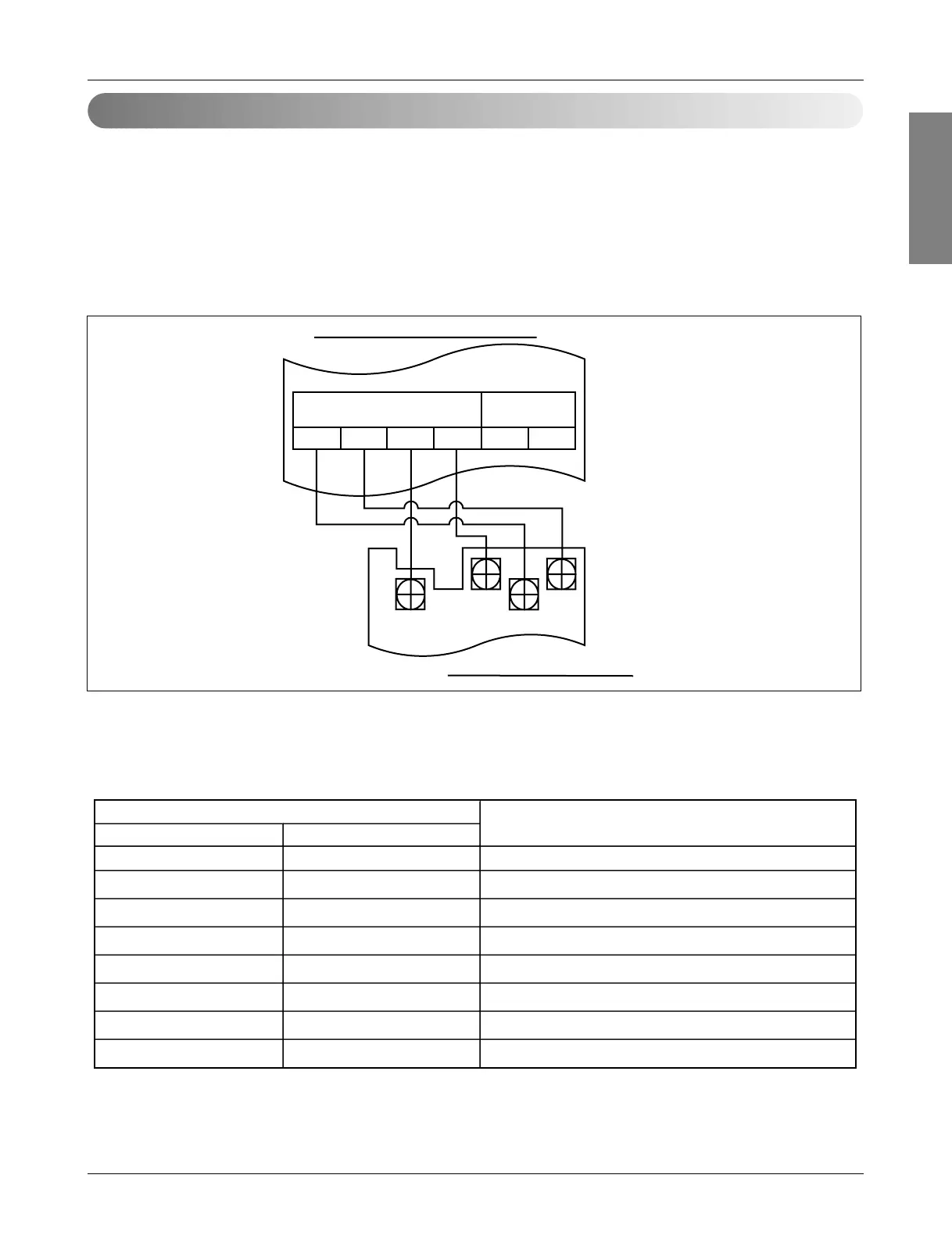
Group Number Setting for Indoor Units
ABGND
12V
Vcc
GND
D
C
C
D
Indoor unitCentral controller
Simple central Controller
Terminal block of outdoor unit
• Group number of each indoor unit is set with rotary switch of control PCB in each indoor unit.
• Before power is supplied, the rotary switch for simple central controller on the indoor unit PCB should be set.
• ID Mapping of Rotary Switch is following table.
SW01M(GROUP) SW02M(UNIT)
Each rotary switch setting in Indoor
Simple central controller recognition
00~F
10~F
20~F
30~F
40~F
50~F
60~F
1
st
Group, 0~F Unit
2
nd
Group, 0~F Unit
3
rd
Group, 0~F Unit
4
th
Group, 0~F Unit
5
th
Group, 0~F Unit
6
th
Group, 0~F Unit
7
th
Group, 0~F Unit
70~F 8
th
Group, 0~F Unit
➀ Confirm the power of whole system(indoor unit, outdoor unit) is OFF, otherwise turn off.
➁ The transmission lines connected to C, D of simple central controller should be connected to C,D terminal port
for central control of outdoor unit with care for their polarity.(C ➔ C, D ➔ D)
➂ DC power line(12V) and ground line should be connected to terminal block of adjacent indoor unit.
➃ Set group number with increasing the rotary switch from 00 to 7F in orderly manner. (if it is desired to control
several indoor units as a group, each group control is possible by group ID rotary switch setting from 0 to 7)
➄ The whole system power turns on.
 Loading...


