- 49 -
Copyright © 2018 LG Electronics Inc. All rights reserved.
Only training and service purposes.
3. Self-diagnosis function
Error Indicator
- This function indicates types of failure in self-diagnosis and occurrence of failure for air condition.
- Error mark is displayed on display window of indoor units and wired remote controller, and 7-segment LED of
Compressor Module control board as shown in the table.
- If more than two troubles occur simultaneously, lower number of error code is first displayed.
- After error occurrence, if error is released, error LED is also released simultaneously.
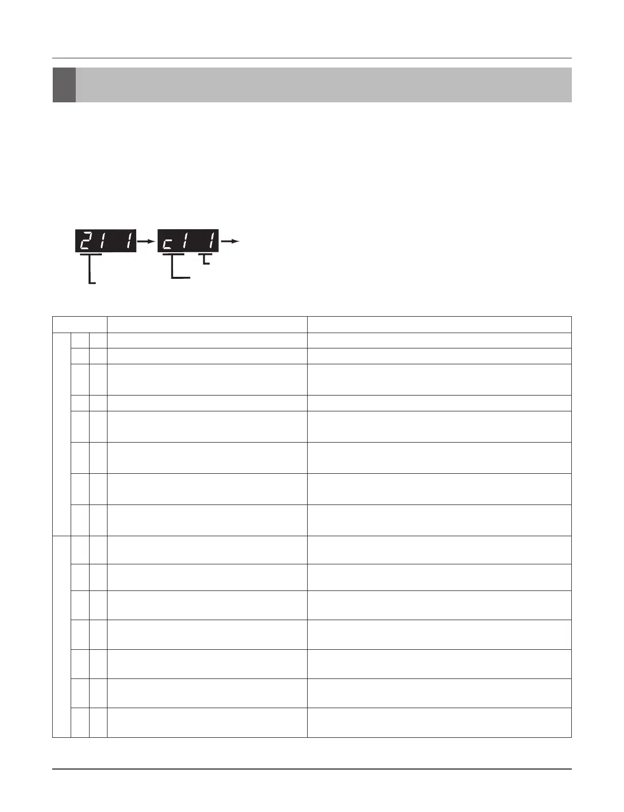
Error Display
1st,2nd,3rd LED of 7-segment indicates error number, 4th LED indicates unit number.
Ex)
*Only applies to Module tpye VRF.
Self-diagnosis function
※ Refer to the Indoor manual for some Indoor Error code.
Display
Title
Cause of Error
Indoor unit related error
0 1
Air temperature sensor of indoor unit
Air temperature sensor of indoor unit is open or short
0 2
Inlet pipe temperature sensor of indoor unit
Inlet pipe temperature sensor of indoor unit is open or short
0 3
Communication error : wired remote
controller ↔ indoor unit
Failing to receive wired remote controller signal in indoor unit
PCB
0 4
Drain pump
Malfunction of drain pump
0 5
Communication error : Compressor
Module ↔ indoor unit
Failing to receive Compressor Module signal in indoor unit
PCB
0 6
Outlet pipe temperature sensor of indoor
unit
Outlet pipe temperature sensor of indoor unit is open or
short
0 9
Indoor EEPROM Error
In case when the serial number marked on EEPROM of
Indoor unit is 0 or FFFFFF
1 0
Poor fan motor operation
Disconnecting the fan motor connector/Failure of indoor fan
motor lock
MULTI V M related error
2 1
Compressor Module Inverter Compressor IPM
Fault
Compressor Module Inverter Compressor Drive IPM Fault
2 2
Inverter Board Input Over Current(RMS) of
Compressor Module
Compressor Module Inverter Board Input Current excess
(RMS)
2 3
Compressor Module Inverter Compressor
DC link Low Voltage
DC charging is not performed at Compressor Module after
starting relay turn on.
2 4
Compressor Module High Pressure Switch
System is turned off by Compressor Module high pressure
switch.
2 5
Compressor Module Input Voltage High/
Low Voltage
Compressor Module input voltage is over 487V or below
270V
2 6
Compressor Module Inverter Compressor
Start Failure
The First Start Failure by Compressor Module Inverter
Compressor Abnormality
2 9
Compressor Module Inverter Compressor
Over Current
Compressor Module Inverter Compressor Fault OR Drive
Fault
 Loading...