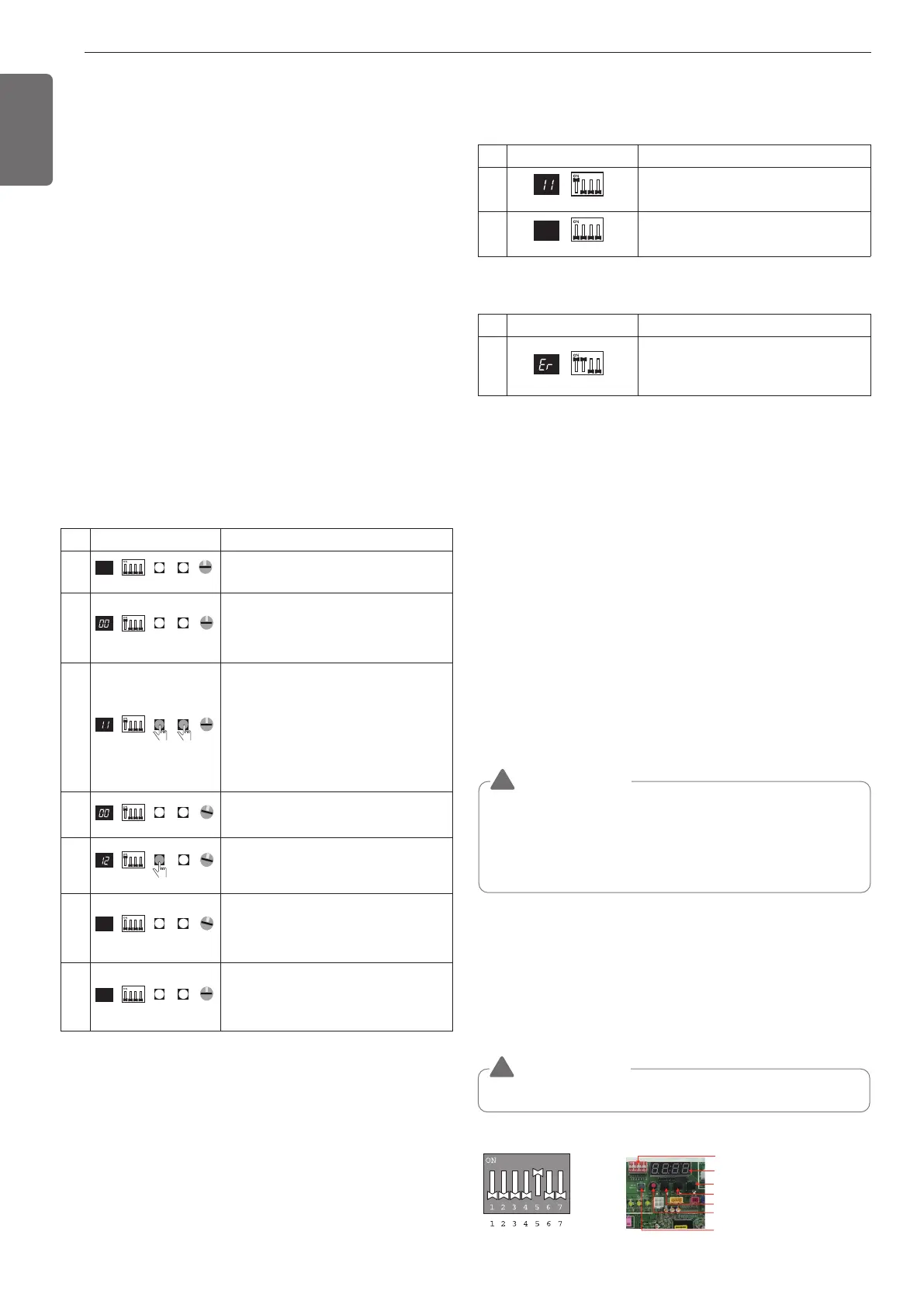
No. Display and setup Setup and Contents
1
- Operation: Turn DIP S/W No.1 on.
- Display: "11" is displayed in 7-SEG
2
- Operation : Turn DIP S/W No.1 off.
- 7-SEG disappeared
No. Display and setup Setup and Contents
1
- Operation: more than 2 DIP switches
turned on.
- Display: "Er" is displayed in 7-SEG
CAUTION
!
• Waiting for 80seconds after power on.
• The zoning information and Master IDU information remove from
EEPROM after Auto-addressing.
• If there is installed the central control, it is impossible setting of
Master IDU in zoning.
Setting method of Master indoor unit in
zoning
1. Master unit PCB DIP switch on: No.5
2. Select the mode using ‘▶’, ‘◀’ Button: "idu" Push the ‘●’ button
3. Select the "id 7" function using ‘▶’, ‘◀’ Push the ‘●’ button
4. select HR unit number and Pipe number as you want to change
- 7-Segment Display "[ x ] [ y ] [ _ ] [ _ ]"
[_]: Blank, [x]: HR unit number, [y]: Pipe number
- Change the HR unit number and Pipe number using ‘▶’, ‘◀’ Push
the ‘●’ button as you want to set
5. Select IDU number as you want
- 7-Segment Display "[ _ ] [ _ ] [ x ] [ y ]"
[_]: Blank, [x]: Indoor unit 10-digit number, [y]: Indoor unit 1-digit
number
- Set the master IDU number using ‘▶’, ‘◀’ Push the ‘●’ button
as you want to set
Identification of Manual Valve ID (Address)
Example of checking valve address
(In case that an indoor unit of central control address "11" is connected
to a valve #1 of an HR unit)
SW01C (Ɨ: Confirm /
Automatic Addressing)
SW02C (ȭ: backward)
SW04C (X : cancel)
DIP-SW01
7-Segment
SW01D (reset)
SW03C (ȯ: forward)
DIP switch setting
Setting the function
Select the mode/function/option/value using ‘▶’, ‘◀’ Button and
confirm that using the ‘●’ button after DIP switch No.5 is turned on.
CAUTION
!
It is only executed when all indoor units are off.
46
ENGLISH
- Above setup must be done for all HR unit valves.
- The valve that is not connected with any indoor unit should be
addressed with any other number than used address numbers of the
valves connected with indoor units.
(The valves does not work if the address numbers are same.)
No. Display and setup Setup and Contents
1
- Operation: None
- Display: None
2
- Operation : Turn DIP S/W No.1 on to
address valve #1
- Display : Existing value saved in
EEPROM is displayed in 7-SEG.
3
- Operation : Set the digit of 10(1) to the
number in Group High data of the wired
remote control connected to the
corresponding indoor unit to the valve
#1 by pressing left tack S/W.
- Display : Digit increasing with the times
of pressing tack S/W is displayed in left
7-SEG.
4
- Operation : SW05M : 1
- Display : Display former value.
5
- Operation : Setting No. using SW03M
and SW04M, SW05M : 1
- Display : Display setting value.
6
- Operation : Turn DIP S/W No.1 off to
save the address of valve #1
- Display : "11" displayed in 7-SEG
disappears.
7
- Operation : Return valve of addressing
HR unit.
- Display : None
7-SEG SW01M SW03M SW04M
0
SW05M
7-SEG SW01M SW03M SW04M
SW05M
0
7-SEG SW01M SW03M SW04M
SW05M
0
1
7-SEG SW01M SW03M SW04M
SW05M
7-SEG SW01M SW03M SW04M
SW05M
1
7-SEG SW01M SW03M SW04M
SW05M
1
7-SEG SW01M SW03M SW04M
SW05M
0
Example of manual valve addressing (Zoning
setting)
(In case that an indoor unit of central control address "11" is connected
to a valve #1 of an HR unit)
Zoning control is connecting 2 or more indoor units at one pipe of HR
unit. In case of Zoning control, in order to set controls with multiple
indoor units connection uses the rotary switch. Namely, only the rotary
switch changes from same valve set condition and set indoor units
connection.
1 On DIP switch of the corresponding valves and sets the rotary
switch at 0.
2 Setting the number with tact switch.
3 In case of addition of indoor units to same port, increases 1 with
the rotary switch and sets number with tact switch.
4 In case of checking the number which the corresponding valve is
stored, turn on DIP switch and set the number of rotary switch.
5 Indoor units set available 7 per a port(rotary switch 0~6), in case of
setting above of 7 with rotary switch, it will display error.
6 Setting the rotary switch on original condition(HR unit number set
conditions) after all finishing a piping setting.
7 The rotary switch set value of above number of indoor units which
is connected with FF and prevents a malfunction.
(Example: The case where 3 indoor units is connected in piping 1,
sets from rotary switch 0,1,2 and 3,4,5 with FF set)
- Prerequisite for manual valve addressing: central control address
of each indoor unit must be preset differently at its wired remote
control.
ARWM***CAS5