47
ENGLISH
Group Number setting
Group Number setting for Indoor Units
- Confirm the power of whole system(Indoor Unit, Outdoor Unit) is
OFF, otherwise turn off.
- The communication cables connected to CEN.A and CEN.B terminal
should be connected to central control of Outdoor Unit with care for
their polarity (A-A, B-B).
- Turn the whole system on.
- Set the group and Indoor Unit number with a wired remote control.
- To control several sets of Indoor Units into a group, set the group ID
from 0 to F for this purpose.
Outdoor Units (External PCB)
Example) Group number setting
1
st
number indicate the group number
2nd number point out indoor unit number
SODU.B SODU.A IDU.B IDU.A CEN.B CEN.A DRY1 DRY2 GND 12 V
B(D) A(C) BA
1 F
Group Indoor unit
* Functions save in EEPROM will be kept continuously, though the
system power was reset.
To cancel the function you need to set OFF.
Group recognizing the central controller
No.0 group (00~0F)
No.1 group (10~1F)
No.2 group (20~2F)
No.3 group (30~3F)
No.4 group (40~4F)
No.5 group (50~5F)
No.6 group (60~6F)
No.7 group (70~7F)
No.8 group (80~8F)
No.9 group (90~9F)
No. A group (A0~AF)
No. B group (B0~BF)
No. C group (C0~CF)
No. D group (D0~DF)
No. E group (E0~EF)
No. F group (F0~FF)
Mode Function Option Value Action
Remarks
Content
Display1
Content Display2 Content Display3 Content Display4
Implement
Display5
Installation
Cool & Heat
Selector
oFF op1~op2
Selected
the option
--
Change
the set
value
Blank
Saving in
EEPROM
Outdoor unit
address
- - - 0~254
Set the
value
Airflow
Adjusting for
IDU (Heating
capacity up)
on oFF
Selected
the option
--
Target
pressure
Adjusting
oFF op1~op6
Selected
the option
--
Compressor
Max. Frequency
Limit
oFF op1~op9
Selected
the option
--
Central Control
Connection at
Indoor Unit
side
on oFF
Selected
the option
--
Compressor
Input Current
Limit mode
oFF
op1~op10
Selected
the option
--
Geometrical
mode setting
on oFF
Selected
the option
--
Sol. Valve 200
V output
on oFF
Selected
the option
--
Variable water
flow control
on oFF
Selected
the option
--
WARNING
!
• Valve address and central control address of its corresponding
indoor unit should be set identical in manual addressing.
Valve (04)
EX)
Valve (03)
Valve (02)
Valve (01)
Indoor unit (04)
Indoor unit (03)
Indoor unit (02)
Indoor unit (01)
Central control address
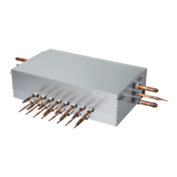
HR unit
Function setting
Master unit PCB DIP switch on : No.5
Select the mode using ‘▶’, ‘◀’ Button :
“Func” Push the ‘●’ button
Select the Function using ‘▶’, ‘◀’ Button :
“Fn1” Push the ‘●’ button
Select the Option using ‘▶’, ‘◀’ Button :
“oFF”,“op1”,“op2” Push the ‘●’ button
Cool & Heat Selection mode is set
Cool & Heat selector (Fn 1)
Mode setting method
Switch Control Function
Switch
(Up)
Switch
(Down)
oFF op1(mode) op2(mode)
Right side
(On)
Left side
(On)
Not operate Cooling Cooling
Right side
(On)
Right side
(On)
Not operate Heating Heating
Left side
(Off)
- Not operate Fan mode Off