26
ENGLISH
- About more information of IO Module, please refer to IO Module
manual.
Be sure to turn off outdoor unit power before installation.
+
+
※Pictures may differ depending on the model.
• Initial display order
• Example) ARUN050GSL0
Order No Note
①
4~12 Model capacity
②
1 Cooling only
2 Heat pump
③
38 380 V
46 460 V
22 220 V
④
1 R410A Standard
2 Compact
5 Cold temperature area
6 Tropical
9 R32 Standard
① ② ③ ④
5 2 22 1
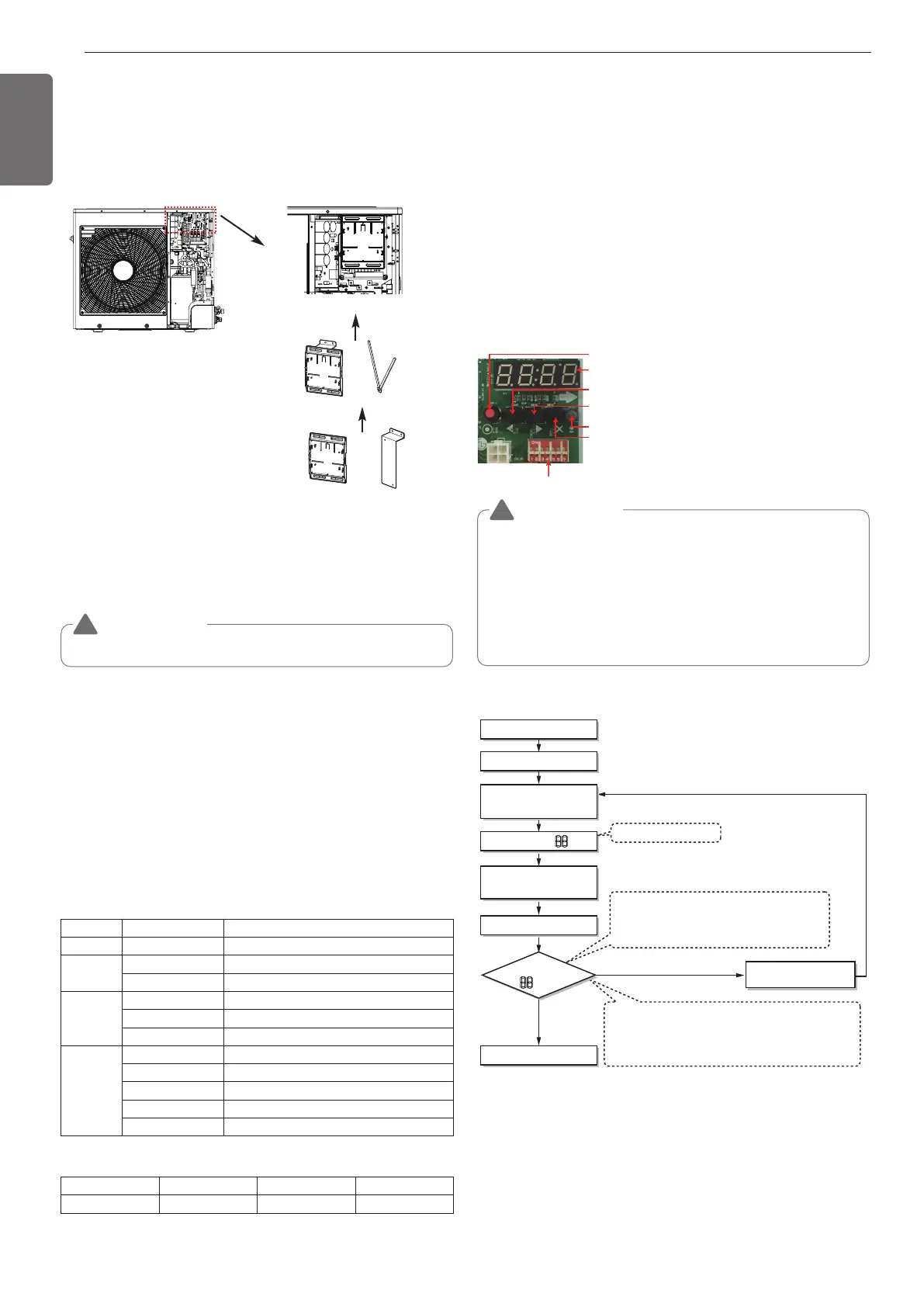
DIP SWITCH
7-Segment
SW01C ( Ɨ: confirm)
SW02C ( ȭ: backward)
SW04C ( X : cancel)
SW01D (reset)
SW03C ( ȯ: forward)
• In replacement of the indoor unit PCB, always perform Automatic
addressing setting again (At that time, please check about using
Independent power module to any indoor unit.)
• If power supply is not applied to the indoor unit, operation error
occur.
• Automatic Addressing is only possible on the master Unit.
• Automatic Addressing has to be performed after 3 minutes to
improve communication.
The Procedure of Automatic Addressing
• Automatic addressing setting end
Numbers of indoor unit connection set whose
addressing is completed are indicated for 30 seconds
on 7-segment LED after completing setting
Indoor address number is displayed on wired remote control or
indoor unit display window. It is not an error message, will
disappeared when on/off button is pressed on remote control
ex) Display of 01, 02, ..., 15 means connection of 15 indoor units
and Automatic addressing is completed normally.
Automatic addressing start
Waiting 3 minutes
Power On
Press RED Button for 5 s
(SW01C)
7-segment LED = 88
Don’t press RED Button
(SW01C)
Waiting about 2~7 minutes
7-segment LED
OK
YES
NO Check the connections
of communication cable
= 88
Automatic Addressing
The address of indoor units would be set by Automatic Addressing
- Wait for 3 minutes after supplying power.
(Master and Slave outdoor units, indoor units)
- Press RED button of the outdoor units for 5 seconds. (SW01C)
- A “88” is indicated on 7-segment LED of the outdoor unit PCB.
- For completing addressing, 2~7 minutes are required depending on
numbers of connected indoor units
-
Numbers of connected indoor units whose addressing is completed are
indicated for 30 seconds on 7-segment LED of the outdoor unit PCB
- After completing addressing, address of each indoor unit is indicated
on the wired remote control display window. (CH01, CH02,
CH03, ……, CH06 : Indicated as numbers of connected indoor units)
[Heat Pump (MAIN PCB)]
Checking the setting of outdoor units
Checking according to DIP switch setting
- You can check the setting values of the Master outdoor unit from the
7 segment LED.
The DIP switch setting should be changed when the power is OFF.
Checking the initial display
The number is sequentially appeared at the 7 segment in 5 seconds
after applying the power. This number represents the setting
condition. (For example, represents R410A 10HP)
Installation of IO Module(optional)
① Assemble IO Module and bracket.
② Fix the bracket on designated location with two clamp cords(105
mm).
③ Connect the connection wires according to the instructions.
(Please refer to Setting and Using Method.)
CAUTION
!
CAUTION
!

 Loading...