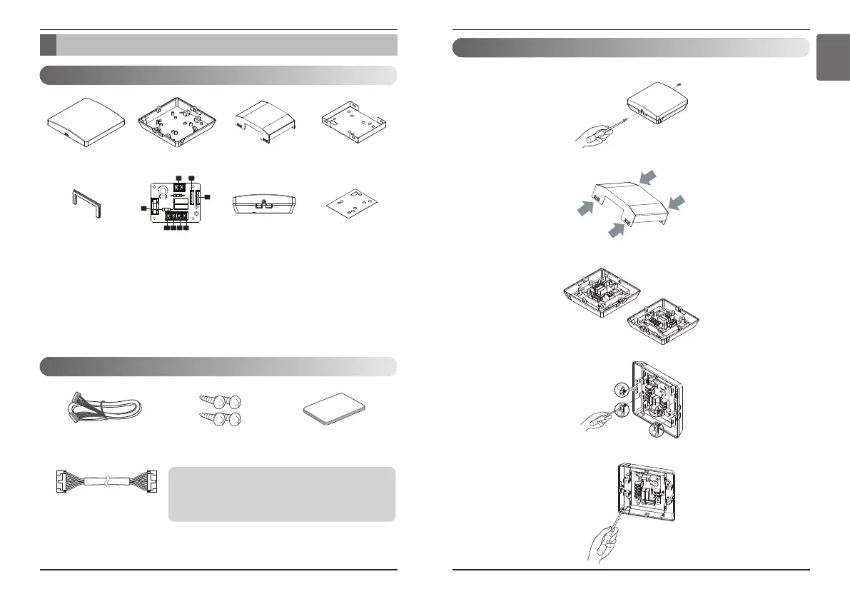
Part Description
10 Dry Contact
Part Description
Installation Manual 11
ENGLISH
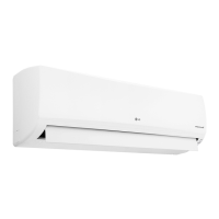
1) Loosen and remove two screws that secures the product.
2)Remove the front metal case by pressing the marked points.
3) Position the rear case to the direction (left or right) towards to the connector
4)Remove 4 screws, for strapping wires.
5) Secure the rear case on the installation place using the supplied fixing screws.
Installation
CN_POWER : Connector
CN_CC : Indoor PCB Connector
CN1 : Central Controller Connector
CN_DRY(L) :
DRY CONTROLLER Connector
CN_DRY(SIG) :
DRY CONTROLLER Connector
CN_DRY(ERROR CHECK) :
ERROR Check Display Connetor
CN_DRY(OPER STATE) :
Operation Display Connector
FUSE : 250 V / 3.15 A
1 2
3
8
4 5 6 7
Front Case Rear Case Metal Case (Front) Metal Case (Rear)
Rubber
PCBA
Side Isolation Sheet
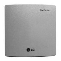
Accessory
*Note
• These cable using for connection between Dry contact and Indoor
unit.
• So before using these things Please check the connector type first
and use cables on proper indoor unit.
Cable 1EA
(for connecting with indoor unit)
Screw
(For installation, 4EA)
User/Installation
Manual
PDRYCB000 (PCB + Case)
Part Description