Do you have a question about the LG PDRYCB500 and is the answer not in the manual?
Critical installation safety advice, including electrical hazards and professional installation requirements.
Warnings regarding installation location, environment, weight capacity, and exposure to elements.
Guidelines for safe operation, focusing on power lines and handling to prevent damage or hazards.
Warnings about water ingress, inundation, and proper usage in specific environments.
Precautions regarding cleaning, disassembly, repair, and handling by children or elderly.
Technical configuration parameters for Modbus communication, including network and baud rate.
List of data registers, their names, ranges, and specific notes for operation and status.
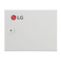
Identification of external parts of the Modbus Gateway, including front, rear, and side views.
Diagram showing the Printed Circuit Board (PCB) layout and numbered connectors/components.
Description of connectors (CN-OUT, BUS-A, BUS-B) and switches (SW1, SWDIP) on the PCB.
Detailed steps for installing the Modbus Gateway inside the indoor unit, including PCB mounting.
Important cautions regarding product placement, screw tightening, and case deformation during installation.
Steps to loosen screws, position the rear case, and prepare for mounting.
Securing the rear case and removing knock-out shapes for cable connectors.
Connecting wires and setting switches as per instructions for proper functionality.
Finalizing case assembly and reiterating cautions on installation surface, screws, and case deformation.
Diagram illustrating the connection between the Dry contact, Indoor unit PCBA, and Modbus Controller.
Guide to setting the Modbus address using the DIP switch for multiple device configurations.
| Brand | LG |
|---|---|
| Model | PDRYCB500 |
| Category | Air Conditioner |
| Language | English |