This document is an installation manual for an LG Air Conditioner, specifically for an Independent Power Kit (PRIP0) used with Multi V Products. It provides essential information for qualified service technicians to ensure safe and efficient installation and operation of the air conditioning system.
Function Description:
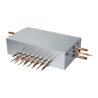
The Independent Power Kit (PRIP0) is an accessory designed to be integrated with various LG indoor air conditioning units, including different types of ceiling cassettes, concealed ducts, wall-mounted units, floor-standing units, and Hydro Kits. Its primary function is to manage the power supply to the Electronic Expansion Valve (EEV) of the indoor unit, ensuring proper operation and control of refrigerant flow. The kit facilitates the electrical connection between the indoor unit's PCB and its EEV, which is crucial for the air conditioner's performance.
Important Technical Specifications:
The manual outlines the components included in the PRIP0 kit:
- Independent Power Kit (PRIP0): 1 unit
- Screw (M4 x 10): 2 units
- Clamp (Tie Wrap): 4 units
- Harnesses:
- Harness 1 (1 m)
- Harness 2 (1 m)
- Harness 3 (1 m)
- Harness 4 (0.05 m)
- Insulator (PE): 2 units
- Installation manual: 1 unit
Dimensions of the PRIP0 unit are provided: 185 mm (length), 98 mm (width), and 48 mm (height).
The manual also specifies the minimum cross-sectional area of conductors for various rated currents of the appliance, ranging from 0.5 mm² for currents up to 3 A (tinsel cord) to 10 mm² for currents up to 63 A. For currents between 6 A and 16 A, cross-sectional areas of 1.0 mm² or 1.5 mm² are specified, with parenthetical values (0.75 mm² or 1.0 mm²) for portable appliances if their length does not exceed 2 m. Tinsel cords are limited to a length of 2 m.
Usage Features:
The installation manual details the assembly process for various indoor unit types:
- High Static Duct/FAU: Involves opening the control box cover, assembling the PRIP0 with the cover, opening the PRIP0 cover to connect wires, and then reassembling the control box cover. Insulation must be attached at the rear of the control box cover where screws are received.
- Low Static Duct/Built-in Duct: Similar steps to the High Static Duct/FAU, with specific chassis dimensions (M1, M2, M3, L1, L2, B1/B3, B2/B4) and corresponding lengths (L) provided for different models.
- 1 Way CST (Ceiling Cassette): Involves opening the control front panel, assembling PRIP0 with the cabinet, opening the PRIP0 cover to connect wires, and then reassembling the control box cover and front panel. Chassis dimensions (TU/TT) and length (L = 510 mm) are specified.
- 2 Way CST (Ceiling Cassette): Similar assembly steps to the 1 Way CST, with chassis dimensions (TS, TL) and corresponding lengths (L = 670 mm, 890 mm) provided.
- 4 Way CST (Ceiling Cassette): Similar assembly steps to the 1 Way CST, with chassis dimensions (TQ/TR, TP/TN/TM/TP-B/TM-A) and corresponding lengths (L = 630 mm, 900 mm) provided. A caution is given to check the attached direction to the indoor unit.
- Ceiling Suspended/Console: Involves mounting the independent power kit on the wall, connecting wires through a piping or wiring hole, and assembling the cover. A critical caution states that the PRIP0 should not be installed in places exposed to rain or water to prevent electric shock, fire, or injury. The independent power kit must be installed within 1000 mm of the indoor unit, corresponding to the length of the provided wires, to prevent EEV malfunction.
- Wall mounted & Art cool: Similar installation instructions to Ceiling Suspended/Console units, with the same cautions regarding exposure to water and installation distance from the indoor unit.
- Hydro Kit: Involves opening the front panel of the control box, assembling the PRIP0 cover, fixing it tightly with bolts, and connecting wires.
Piping installation guidelines are provided, emphasizing the need for pipes between the indoor unit and its branch to incline to prevent backflow. If the indoor unit is located lower than its branch, an Oil Trap must be applied.
Electrical wiring instructions are detailed:
- Turn off power using the circuit breaker.
- Disconnect the EEV cable from the indoor unit's PCB (CN-EEV).
- Connect the independent power kit (CN-EEV/LOAD) to the indoor unit's EEV using harness 1.
- Connect the independent power kit (CN-EEV/MAIN) to the indoor unit's PCB (CN-EEV/CN_WRITE or CN1 or CN1_IPM) using harness 2, 3, or 4, depending on the model.
- Supply power.
Maintenance Features:
The manual emphasizes the importance of proper installation for safe and efficient operation. It advises qualified service technicians to perform all installation and service work. Regular checks for leaks after connecting refrigerant tubing are recommended. During servicing, power must be turned OFF at the main power box, and hands/clothing should be kept away from moving parts. The site should be cleaned thoroughly, ensuring no metal scraps or wiring bits are left inside the unit.
Safety Precautions:
The manual includes extensive safety warnings and cautions:
- WARNING: Indicates the possibility of death or serious injury.
- Installation information is for qualified service technicians.
- Failure to follow instructions can result in equipment malfunction, property damage, personal injury, or death.
- Electrical shock can cause severe personal injury or death; only qualified electricians should wire the system.
- Do not supply power until all wiring and tubing are complete and checked.
- Highly dangerous electrical voltages are used; refer to wiring diagrams and instructions.
- Ground the unit according to local electrical codes.
- Connect all wiring tightly to prevent overheating and fire hazards.
- Be careful when transporting units; use a partner and bend knees when lifting. Sharp edges or thin aluminum fins can cause cuts.
- Electric works must be carried out by qualified personnel according to "The technology requirement on the electric installation" and wiring standards.
- Incomplete installation or insufficient power circuit capacity can cause electric shock, fire, death, or injury.
- User-performed installation may lead to incompleteness, causing electric shock, fire, injury, and death.
- Do not perform electric work or put hands/fingers into the machine when power is applied.
- The wire should not be exposed to the outside to prevent malfunction or damage to the independent power kit.
- Wrong wiring can cause malfunction or damage to the independent power kit.
- Power must be supplied continuously for more than 20 minutes for the independent power kit to operate correctly; otherwise, the EEV may not fully close due to lack of charging power.
- CAUTION: Indicates the possibility of injury or damage.
- Improper installation, adjustment, alteration, service, or maintenance can void the warranty.
- Use caution when lifting or moving the condensing unit due to its weight.
- Always wear safety eyewear and work gloves.
- Never assume electrical power is disconnected; always check with a meter.
- Keep hands out of fan areas when power is connected.
- R-410A causes frostbite burns and is toxic when burned.
- Read the manual completely before installation.
- Check all included items before installation; use certified products for items not provided by LG.
- If the supply cord is damaged, it must be replaced by the manufacturer, service agent, or similarly qualified persons.
- Means for disconnection must be incorporated into fixed wiring according to wiring rules.
- Do not install the unit in potentially explosive atmospheres.
- This appliance is not intended for use by persons with reduced physical, sensory, or mental capabilities, or lack of experience/knowledge, unless supervised or instructed. Children should be supervised not to play with the appliance.
- Ensure the wall is strong enough to hold the unit's weight when installing in a wall.
- Properly insulate tubing run inside a room to prevent "sweating."
- Use a raised concrete pad or blocks for outdoor units in moist or uneven locations.
- Securely anchor outdoor units in areas with high winds and provide an air baffle.
- Install outdoor units on a raised platform in snowy areas.
- Keep tubing runs as short as possible.
- Use the flare method for connecting tubing.
- Check for leaks before the test run.
- Check the distance between PRIP0 and the control box when connecting anchor bolts.
- Check the attached direction to the indoor unit.
- Do not install PRIP0 in places exposed to rain or water to prevent electric shock, fire, injury, or fatality.
- The independent power kit must be installed within 1000 mm (length of given wires) to prevent indoor EEV malfunction.
The manual also notes that pipes and wires should be purchased separately for product installation.