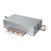
Assembly Diagram
Installation Manual 13
ENGLISH
n 4 Way CST
Step1. Open control front panel. Step2. Assemble PRIP0 with cabinet.
Step3. Open the cover of PRIP0 and connect wires. Step4. Assemble control box cover and front panel.
Fig. A
Control box cover
screw
Insulation
Note: While connecting the PRIP0, attach insulation at the rear of the control box cover
where it receives screws as shown in Fig. A.
Check the attached direction to the indoor unit.
(Unit : mm)
chassis L
TQ/TR 630
TP/TN/TM/TP-B/TM-A 900
CAUTION
!
 Loading...