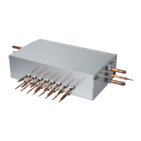
10 Independent Power Kit
Assembly Diagram
n Low Static Duct/Built-in Duct
Fig. A
Control box cover
screw
Insulation
Note: While connecting the PRIP0, attach insulation at the rear of the control box cover
where it receives screws as shown in Fig. A.
Step1. Open control box cover. Step2. Assemble PRIP0 with control box cover.
Step3. Open the cover of PRIP0 and connect wires. Step4. Assemble control box cover.
(Unit : mm)
Check the distance between PRIP0 and the top of model
when connecting anchor bolts.
Chassis L
M1 1 090
M2 1 350
M3 1 400
L1 1 090
L2 1 350
B1/B3 1 090
B2/B4 1 350
CAUTION
!
 Loading...