2-8
Copyright © 2022 LG Electronics Inc. All rights reserved.
Only for training and service purposes.
HOW TO ASSEMBLE THE BOTTOM HOUSING
A
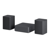
1-4. ASSEMBLE OF LED PCB
Step 1. Assemble Red points Screw(CTB3+6GFZR) : 2 EA [Closing torque : 5.0 ± 0.5kgf.cm]
Step 2. Assemble Blue point LED wire Jack and insert the wire into the groove. (A)
Step 1
Step 2
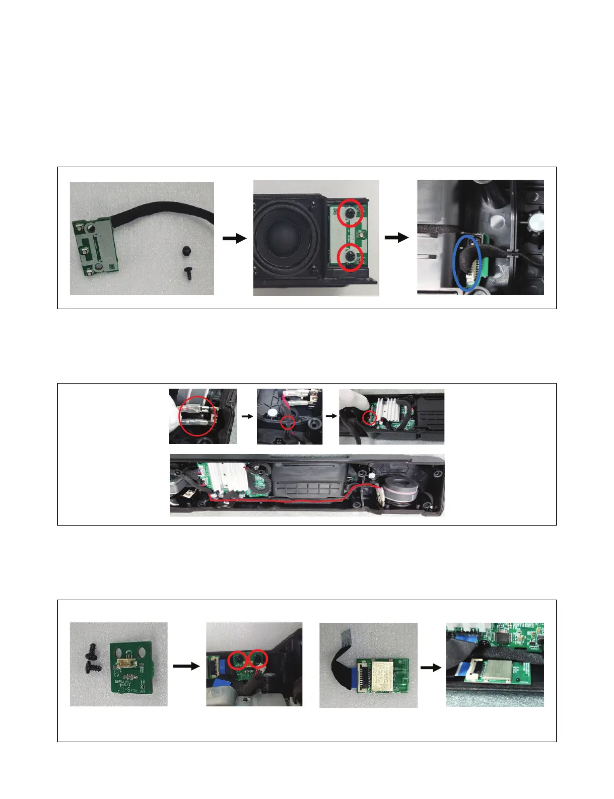
1-6. ASSEMBLE OF REMOTE PCB AND BT MODULE
Step 1. Assemble Red points Screw(CTB3+6GFZR, 2 EA) and connect jack.
Step 2. Assemble the BT Module and connect jack. (It is glued with double-sided tape.)
Step 1
Step 2
Step 3
Step 4
Step 1
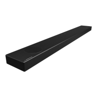
1-5. ASSEMBLE OF CORD WIRE (R Side)
Step 1. Assemble the speaker terminal. Step 2. Insert the speaker line in the groove.
Step 3. Connect the speaker line to the main PCB. Step 4. Please arrange the line along the red line.
 Loading...